With some basic knowledge of how the IS31FL3728 works, let’s tackle how to get it displaying LED patterns, numbers and colors.
Background
I2C Basics
Changing the I2C Library
IS31FL3728 Datasheet
Bit Shifting
Bit Masking
IS31FL3728 Register Used for Display LED Patterns and Digits
There are eight registers available that control chunks of LEDs, and those chunks are divided up by digit on the seven segment display, and by color on the bar graph.
| Item | Register Address |
|---|---|
| Bar Graph – Red | 0x01 |
| Bar Graph – Green | 0x02 |
| Bar Graph – Blue | 0x03 |
| Digit 0 | 0x08 |
| Digit 1 | 0x07 |
| Digit 2 | 0x06 |
| Digit 3 | 0x05 |
| Misc. LEDs | 0x04 |
Each register is 8 bits long, with each bit controlling the on / off state of the LEDs in it’s respective chunk. They are mapped out as follows.
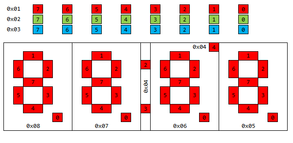
If you wanted the second digit from the left to display the number “3”, you would write a value to register 0x07 that corresponds to the first, second, third, fourth and seventh bit being set equal to 1 and all the others equal to 0 (remember, when determining bit position, you count from right to left starting with 0): B10011110. Converting that to hex = 0x9E.
All the Hex Numbers
By going through each number 0-9 and then the hex characters A-F, you can quickly build a table of bit patterns that can be written to the digit registers to display a specific number. I’ve gone and figured them all out for you.
| Character | Binary | Hex | Decimal |
|---|---|---|---|
| 0 | B01111110 | 0x7E | 123 |
| 1 | B00001100 | 0x0C | 012 |
| 2 | B10110110 | 0xB6 | 182 |
| 3 | B10011110 | 0x9E | 158 |
| 4 | B11001100 | 0xCC | 204 |
| 5 | B11011010 | 0xDA | 218 |
| 6 | B11111010 | 0xFA | 250 |
| 7 | B00001110 | 0x0E | 014 |
| 8 | B11111110 | 0xFE | 254 |
| 9 | B11011110 | 0xDE | 222 |
| A | B11101110 | 0xEE | 238 |
| b | B11111000 | 0xF8 | 248 |
| C | B01110010 | 0x72 | 114 |
| d | B10111100 | 0xBC | 188 |
| E | B11110010 | 0xF2 | 242 |
| F | B11100010 | 0xE2 | 226 |
Note that the hex characters for b and d are lower case because B looks just like 8 and D looks just like 0.
A Constant Array
Since the values are sequential 0-15 (or just 0-9 if you don’t care about hex values), you can just load them into an array, and provided you prepare the array in an organized fashion, you’ll be able to grab the pattern you want by placing that value at the corresponding index.
|
1 2 |
// 0 1 2 3 4 5 6 7 8 9 const byte numPatterns[20] = {0x7E, 0x0C, 0xB6, 0x9E, 0xCC, 0xDA, 0xFA, 0x0E, 0xFE, 0xDE}; |
|
1 2 |
// 0 1 2 3 4 5 6 7 8 9 A b C d E F const byte numPatterns[32] = {0x7E, 0x0C, 0xB6, 0x9E, 0xCC, 0xDA, 0xFA, 0x0E, 0xFE, 0xDE, 0xEE, 0xF8, 0x72, 0xBC, 0xF2, 0xE2}; |
By placing that in the declarations area of your sketch, you’ll be able to write a number pattern to the display from anywhere in your sketch.
To make developing patterns a little easier, I’ve put together this excel file that allows you to set the pattern you want to see, then spits out the hex / binary / decimal value that is the equivalent of it. It also has the number patterns listed above, and the color codes listed below: I2C_Display_v2_Pattern_Generator
RGB LEDs
The RGB LEDs in the bar graph at the top are pretty easy to write to, since they are laid out exactly the same as the bits of their register addresses. So if you wanted to turn on the third red LED from the left and the sixth blue LED, you would send the value B00000100 to register 0x01 and value B01000000 to register 0x03.
By combining multiple colors at once at each pixel location, you can create more than just Red, Blue and Green, you can have Cyan, Magenta, Yellow and White as well.
- RED + BLUE = MAGENTA
- RED + GREEN = YELLOW
- BLUE + GREEN = CYAN
- RED + BLUE + GREEN = WHITE
The trick is figuring out how to easily change between those values.
Displaying RGB LED Patterns Control
The method I came up with is to write a function that takes the pixel position you want to change, and the color you want to change it to. It makes extensive use of bit masking and bit shifting you may want to review those pages if you haven’t used those techniques in a while.
The first difficulty that we run into is that the column registers are write-only. So once you’ve sent a pattern to a register for display, you can’t read that register back to see what’s playing there. That means we have to keep track of it ourselves. So in our declarations area, we’ll create some byte variables to hold the current pattern for us to manipulate, along with some user friendly values for the ISSI I2C Address and the registers we need to play with. There also needs to be a variable created for the shutdown pin so we can control it.
|
1 2 3 4 5 6 7 8 9 10 11 12 13 14 15 16 17 |
#include const byte IS31FL3728_I2C = 0x60; // IS31FL3728 I2C Address and Registers. Driver Address Pin is Tied Low. const byte IS31_R_CONFIG = 0x00; // Configuration Register const byte IS31_R_BRIGHT = 0x0D; // Brightness / Audio Gain Register const byte IS31_R_UPDATE = 0x0C; // OpCode used to latch display update const byte DUMMY_DATA = 0xCC; // OpCode needs to be sent dummy value const byte TOP_R = 0x01; // top RED LEDs in RGB die const byte TOP_G = 0x02; // top GRN LEDs in RGB die const byte TOP_B = 0x03; // top BLU LEDs in RGB die byte valueTopR = 0; byte valueTopG = 0; byte valueTopB = 0; const byte pinShutdown = A3; |
Our setup is pretty straight forward: drive the shutdown pin high, configure I2C appropriately, configure the ISSI for 8×8 matrix mode with no audio in normal operation, and set the brightness to the lowest value. Finally, we need to blank the display, because it maintains the state of its registers through pretty much any event besides power off. Remember you have to send dummy data to the update register in order for the display to actually show the new patterns.
|
1 2 3 4 5 6 7 8 9 10 11 12 13 14 15 16 17 18 19 20 |
void setup() { pinMode (pinShutdown, OUTPUT); // Configure the shutdown pin as output digitalWrite (pinShutdown, HIGH); // Enable the display I2c.begin (); // Initialize the I2C library I2c.pullup (1); // Enable the internal pullup resistors I2c.setSpeed (0); // Enable 100kHz I2C Bus Speed I2c.timeOut (250); // Set a 250ms timeout before the bus resets I2c.write(IS31FL3728_I2C, IS31_R_CONFIG, 0x00); // Configure Driver for Normal Operation, Audio Disabled, 8x8 Matrix Mode I2c.write(IS31FL3728_I2C, IS31_R_BRIGHT, 0x08); // Configure brightness to lowest value // Write zeros to all the bits of each display register: 0x01 through 0x08 for (int i = 1; i < 9; i++) { I2c.write(IS31FL3728_I2C, i, 0x00); } I2c.write(IS31FL3728_I2C, IS31_R_UPDATE, DUMMY_DATA); } |
setRGB Function
Our function needs to accept two parameters: the position of the pixel we want to change the color of, and the color we want to change it to. The pixel position is easy, 7-0 corresponds to the way the LEDs are laid out on the physical PCB, so we’ll call that pixelPosition. For the color value, we have 8 different colors we can select from 0 to 7, so that means we can cover all of those with a three bit value, that we’ll call pixelColor. Since RGB is easy to remember, we’ll use that pattern for the number that we send. So if we want to turn a pixel MAGENTA, then Red would be 1, Green would be 0, and Blue would be 1: B101, hex 0x03.
To make it easy for us to reference, we can define the color values up in the declarations area with human readable names.
|
1 2 3 4 5 6 7 8 |
#define BLK 0x00 #define RED 0x04 #define GRN 0x02 #define BLU 0x01 #define YLW 0x06 #define MAG 0x05 #define CYA 0x03 #define WHT 0x07 |
Within the function, the first thing we need to do is separate out the individual states of each color channel. We can do that by ANDing the pixel color a few times with a mask for each color position, then shifting the value over to the 1s place.
|
1 2 3 4 |
// Determine the desired state of each color byte rValue = (pixelColor & 0x04) >> 2; byte gValue = (pixelColor & 0x02) >> 1; byte bValue = (pixelColor & 0x01); |
Now that we know what we want to do with each color, we have to update those pattern variables we created in the declarations area. If the value is a 0, then we need to make sure that bit is cleared in the pixelPosition that was sent, if the value is a 1, then we need to set the bit in that pixel position.
|
1 2 3 4 5 6 7 |
// Sets or clears bits depending on the state of the color in that position if (rValue == 0) valueTopR &= ~(0x01 << pixelPosition); if (gValue == 0) valueTopG &= ~(0x01 << pixelPosition); if (bValue == 0) valueTopB &= ~(0x01 << pixelPosition); if (rValue == 1) valueTopR |= (rValue << pixelPosition); if (gValue == 1) valueTopG |= (gValue << pixelPosition); if (bValue == 1) valueTopB |= (bValue << pixelPosition); |
Now that we have our colors determined, and moved to the current location in the pixel map, all we have left to do is write those values to the RGB registers, and send the update command.
|
1 2 3 4 |
I2c.write(IS31FL3728_I2C, TOP_R, valueTopR); I2c.write(IS31FL3728_I2C, TOP_G, valueTopG); I2c.write(IS31FL3728_I2C, TOP_B, valueTopB); I2c.write(IS31FL3728_I2C, IS31_R_UPDATE, DUMMY_DATA); |
Main Loop
Within our loop, let’s just test that we got everything right by writing one color to each pixel, from black to white.
|
1 2 3 4 5 6 7 8 9 10 11 12 |
void loop() { setRGB(0, BLK); setRGB(1, RED); setRGB(2, GRN); setRGB(3, BLU); setRGB(4, YLW); setRGB(5, MAG); setRGB(6, CYA); setRGB(7, WHT); } |
When you run the full sketch, you should see each pixel displaying a different color from our gamut of 8 colors.
Full Sketch
|
1 2 3 4 5 6 7 8 9 10 11 12 13 14 15 16 17 18 19 20 21 22 23 24 25 26 27 28 29 30 31 32 33 34 35 36 37 38 39 40 41 42 43 44 45 46 47 48 49 50 51 52 53 54 55 56 57 58 59 60 61 62 63 64 65 66 67 |
/* A sketch that performs color mixing with the RGB bar graph of the I2C Display v2 board. https://rheingoldheavy.com/i2c-display-add-on-tutorial-02-larson-scanner/ */ #include #define BLK 0x00 #define RED 0x04 #define GRN 0x02 #define BLU 0x01 #define YLW 0x06 #define MAG 0x05 #define CYA 0x03 #define WHT 0x07 const byte IS31FL3728_I2C = 0x60; // IS31FL3728 I2C Address and Registers. Driver Address Pin is Tied Low. const byte IS31_R_CONFIG = 0x00; // Configuration Register const byte IS31_R_BRIGHT = 0x0D; // Brightness / Audio Gain Register const byte IS31_R_UPDATE = 0x0C; // OpCode used to latch display update const byte DUMMY_DATA = 0xCC; // OpCode needs to be sent dummy value const byte TOP_R = 0x01; // top RED LED in RGB die const byte TOP_G = 0x02; // top GRN LED in RGB die const byte TOP_B = 0x03; // top BLU LED in RGB die byte valueTopR = 0; byte valueTopG = 0; byte valueTopB = 0; const byte pinShutdown = A3; void setup() { pinMode (pinShutdown, OUTPUT); // Configure the shutdown pin as output digitalWrite (pinShutdown, HIGH); // Enable the display I2c.begin (); // Initialize the I2C library I2c.pullup (1); // Enable the internal pullup resistors I2c.setSpeed (1); // Enable 100kHz I2C Bus Speed I2c.timeOut (250); // Set a 250ms timeout before the bus resets I2c.write(IS31FL3728_I2C, IS31_R_CONFIG, 0x00); // Configure Driver for Normal Operation, Audio Disabled, 8x8 Matrix Mode I2c.write(IS31FL3728_I2C, IS31_R_BRIGHT, 0x08); // Configure brightness to lowest value // Write zeros to all the bits of each display register: 0x01 through 0x08 for (int i = 1; i < 9; i++) { I2c.write(IS31FL3728_I2C, i, 0x00); } I2c.write(IS31FL3728_I2C, IS31_R_UPDATE, DUMMY_DATA); } void loop() { setRGB(0, BLK); setRGB(1, RED); setRGB(2, GRN); setRGB(3, BLU); setRGB(4, YLW); setRGB(5, MAG); setRGB(6, CYA); setRGB(7, WHT); } void setRGB(uint8_t pixelPosition, uint8_t pixelColor) { // Determine the desired state of each color byte rValue = (pixelColor & 0x04) >> 2; byte gValue = (pixelColor & 0x02) >> 1; byte bValue = (pixelColor & 0x01); // Sets or clears bits depending on the state of the color in that position if (rValue == 0) valueTopR &= ~(0x01 << pixelPosition); if (gValue == 0) valueTopG &= ~(0x01 << pixelPosition); if (bValue == 0) valueTopB &= ~(0x01 << pixelPosition); if (rValue == 1) valueTopR |= (rValue << pixelPosition); if (gValue == 1) valueTopG |= (gValue << pixelPosition); if (bValue == 1) valueTopB |= (bValue << pixelPosition); I2c.write(IS31FL3728_I2C, TOP_R, valueTopR); I2c.write(IS31FL3728_I2C, TOP_G, valueTopG); I2c.write(IS31FL3728_I2C, TOP_B, valueTopB); I2c.write(IS31FL3728_I2C, IS31_R_UPDATE, DUMMY_DATA); } |
If you prefer something a bit more dynamic, change your main loop to the following
|
1 2 3 4 5 6 |
void loop() { setRGB(random(0,8), random(0,8)); delay(50); } |
For more I2C Display tutorials, Click Here.