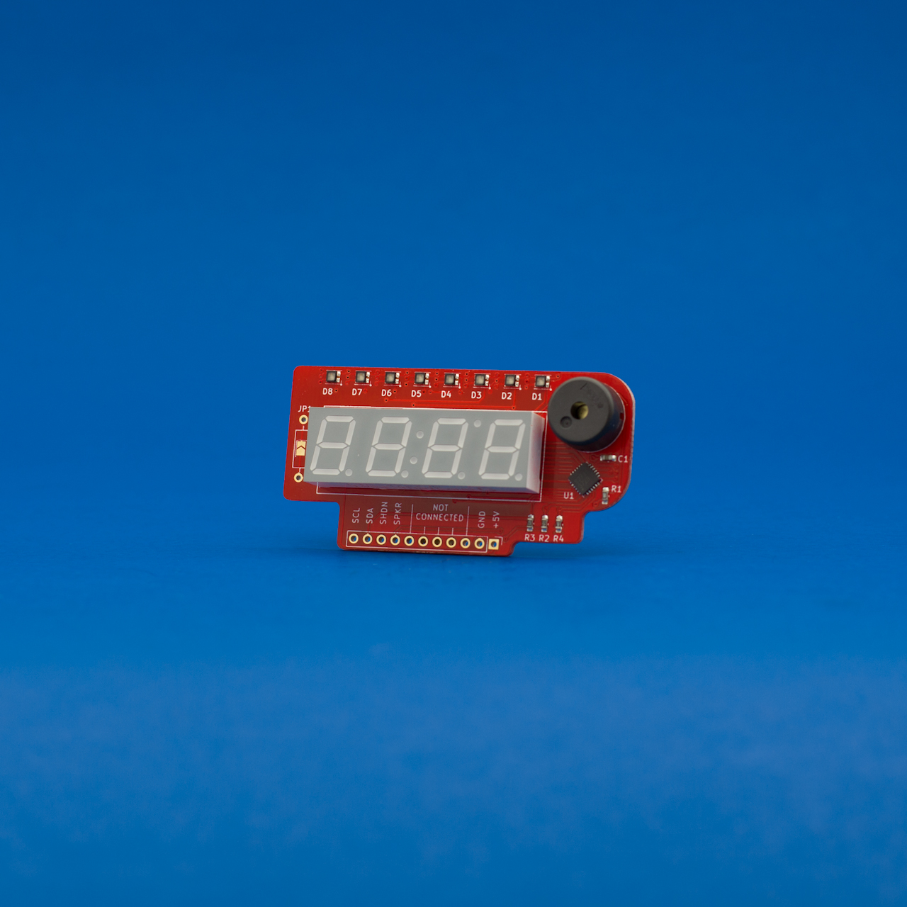
The I2C Display Add-on v2 is a full featured and incredibly versatile LED display featuring the ISSI IS31FL3728 display driver, a four digit seven-segment display, a bar graph of Red / Green / Blue (RGB) LEDs and a piezo speaker.
The Chip
The IS31FL3728 chip is designed to control LED matrixes, in the case of the I2C Display, the matrix is comprised of 64 LEDs. It is configured to control each segment of each digit individually allowing you to create each number as well as dashes and degree symbols. Each color pixel of the RGB LEDs can be controlled separately as well. Brightness of the entire display is variable in 16 levels through code, as well as easy on/off functionality through the use of the SHUTDOWN pin.
The I2C Display Add-on ships with an 11 pin right angle header included, but not soldered in place to save manufacturing costs. If you would like us to solder the header for you, please select the $3.00 “Assembled” option above.
The Seven Segment Display
The display has four digits arranged in the standard seven segment fashion, all connected to the IS31FL3728 in the typical A-G + decimal fashion. In addition to showing the number segments, the display also has decimal places for each digit position as well as a colon to display time.
Bar Graph
The bar graph is built with a row of RGB LEDs that are also controlled by the IS31FL3728, except as individual LEDs instead of as digits. Through combinations of colors and brightness levels, it’s easy to create a threshold display (eg: first five green, last three red), or an audio peak meter using the MSGEQ7 breakout boards. The bar graph is designed to be used simultaneously with the seven segment display so everything can be turned on at once.
Piezo Buzzer
It wouldn’t have been nearly as fun if it didn’t make noise and play sounds! By having the display show time, and integrating it with the MCP7940 Real Time Clock, you can build a groovy alarm clock with only two breakout boards, an Arduino, and some jumper wires.
Connection
The pin header is breadboard compatible at 0.1″” spacing, but is specifically designed to connect directly to the voltage and analog side of an Arduino Uno (or compatible shield). In this configuration, it directly connects, 5V, GND, the I2C pins, and uses A3 to control the IS31FL3728 SHUTDOWN pin and A2 to control the piezo. The remaining pins aren’t connected to the board electrically, they are only there for mechanical stability.
Product Notes
Pull Up Resistors
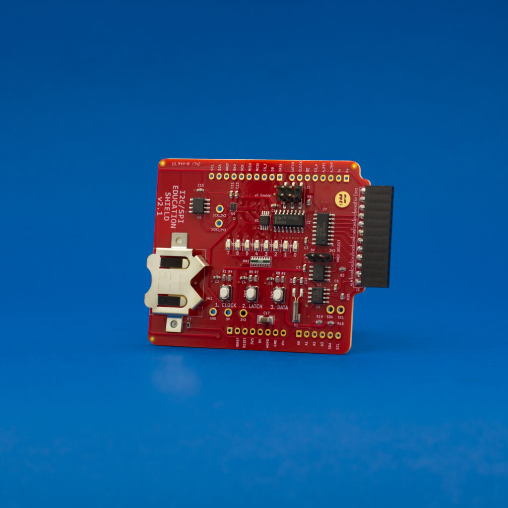
The I2C Display Add-on v2 has 0603 footprints for pull up resistors, but they are not populated. If you want to add pull resistors, solder appropriate value resistors to the R2 and R3 pads, and then short the jumper to the right of the display. The Display works perfectly as-is with the I2C and SPI Education Shield, and directly with the Arduino itself, using the internal pull up resistors which can be configured using the I2C Library.
Pin Connection with Newer UNO R3
Plugging the Display directly into an Arduino UNO R3 works great, however on some of the newer UNOs, a single full header is used from IOREF to A5, with a solid blank between VIN and A0. If that is the case, you can easily clip the pin on your header if it’s already soldered in place, or snap the 11 pin header that came with your Display into three pieces: one 6 pin length (soldered to A0-A5), one 4 pin length (soldered to 5V-Vin), and a single pin you can save in your junk bin.
Functionality and Tutorials
For information about the original version of the I2C Display Add-on, please visit this page: I2C Display v1 Functionality Overview.
Reviews
There are no reviews yet.