Reading temperature from the AT30TS750A is easy now, and so should be managing the configuration. It’s time to do something practical with our sensor and use it as a temperature alarms. Hang on to your hat, this one is going to be a in depth!
Objectives
- Understand the operation of the sensor when configured in comparator mode.
- Configure the fault tolerance and temperature limits to work as a temperature alarm.
- Understand how to use interrupts to capture and react to the AT30TS750A alarm.
- Use the shift register and LEDs to display the alarm status, as well as the serial monitor.
- Use buttons on the Education Shield as digital inputs.
Background
I2C Basics
AT30TS750A Functionality Overview
Retrieving Temperature Value
Atmel AT30TS750A Datasheet
Schematic
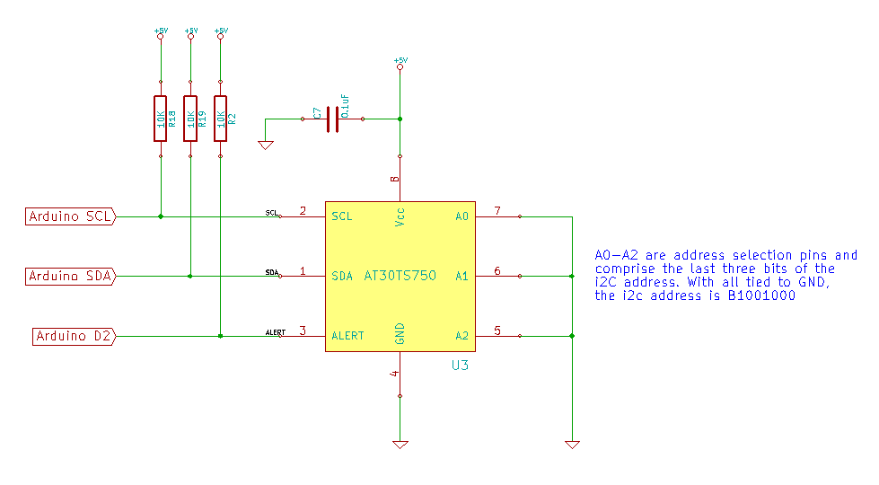
Education Shield – AT30TS750A Temperature Sensor Subsystem
Education Shield – Shift Register Subsystem
Setup
For this module, you’ll need the following equipment:
- I2C and SPI Education Shield or the AT30TS750A and Debounce Button Breakout Boards
- Arduino UNO R3
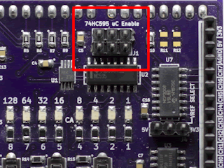
1. Place jumpers on the 74HC595 Enable block along the edge of the Education Shield. This will enable the microcontroller to read button presses.
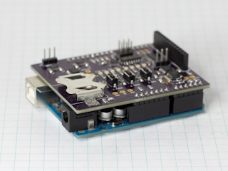
2. Mate the Education Shield with your Arduino UNO R3. If you’re using the AT30TS750A Breakout Board and the Debounce Button Breakout Board, check the labels by the pins and for the AT30TS750A connect 5V to 5V, GND to GND, SC to Analog 5, SD to Analog 4 and AL to Digital2 and for the Debounce Button Board, connect 5V to 5V, GND to GND, and B1 to Digital8 and B2 to Digitl7.
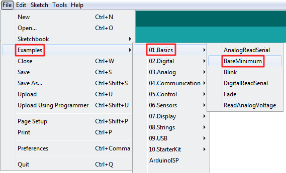
3. Finally, connect your Arduino to your USB cable, and use the Arduino IDE to upload the “Bare Minimum” sketch from the Basics section of the Examples.
The AT30TS750A Alarms System
To be able to plan and build our AT30TS750A temperature alarms, we need to understand the five aspects to the AT30TS750A alert system, configured in three locations, and how to respond to this with the interrupt system of the Arduino. First we’ll cover the sensor alert configurations.
If you haven’t already, or need a reminder, it would be helpful to read the AT30TS750A Functionality Overview module, so you have a solid understanding of the theory of the temperature limits, the interrupt and comparator modes and the fault tolerance settings.
The way in which these items are configured is critical to get right — in some cases, sending incomplete data will cause the sensor to completely abandon the configuration, leaving everything at default.
Alert Mode
The Alert Mode is specified in bit 9 of the Configuration Register 0x01. Specifying a 0 (the factory default) will enable comparator mode and specifying a 1 will enable interrupt mode. We are going to use comparator mode for our tests.
Fault Tolerance
The Fault Tolerance level is specified in bits 11-12 of the Configuration Register 0x01. The tolerance level can be set to the following levels…
| Value | Configuration |
|---|---|
| 0x00 | Trigger alarm after 1 detection |
| 0x01 | Trigger alarm after 2 detections |
| 0x10 | Trigger alarm after 4 detections |
| 0x11 | Trigger alarm after 6 detections |
We will be using a fault tolerance of two in our tests.
Upper and Lower Temperature Limits
These are the limits the comparator will use to determine if the sensor should be in an alarm state or not. The Upper Limit Register, 0x03 and the Lower Limit Register 0x02, are both 16 bits wide, and you must write all 16 bits to the register otherwise the sensor will abandon the configuration and return to defaults.
Our code will sample the temperature at power up, and set the upper limit to “current temperature + 2°C” and set the lower limit to “current temperature + 1°C”. This will allow us to easily trigger and untrigger the alert system for testing.
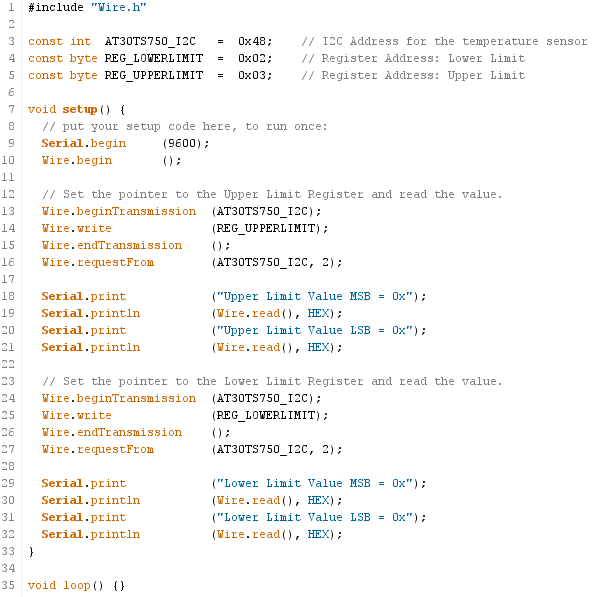
Write a quick sketch to read the default temperature limits immediately after power up. (click here for a picture of the code)
Interrupts
Interrupts are just that… things that interrupt the code flowing on your Arduino. Regardless of anything else your Arduino might be doing, if it detects the change you specify on either Digital3 (referred to as Interrupt0) or Digital4 (referred to as Interrupt1), it will immediately stop everything and execute the code you specify called an “interrupt service routine”, an ISR. It is crucial that the code in your ISR is very, very short — no more than a line or two — because while you’re in the ISR, nothing else can process… so just a blip of code, and don’t even think of doing any delaying or waiting in there!
For our purposes here, we are going to interrupt when there is a state change on the alarm pin of the AT30TS750A, which I connected to Digital3, Interrupt0, on the Education Shield. This will wind up creating a crude, but effective state machine.
State Machines are an incredibly complex topic in which you could easily lose yourself and create an entire career. More information can be read here: Introduction to Finite State Machines
AT30TS750A Temperature Alarms Design Goals
Let’s clearly define what we expect from our temperature sensor. It’s been very kind to us this far and it deserves that much forethought…
- Trigger the alert pin when the temperature rises above the Upper Limit value.
- Operate the alert system in comparator mode.
- The upper limit should be two degrees above the temperature at startup.
- The lower limit should be one degree above the temperature at startup.
- The fault tolerance should require two measurements in order to create the alert.
- Turn the Education Shield LEDs to turn on in the event of an alarm and off when the alarm has passed.
- Measure the temperature when we press the DATA button.
- Issue a general call reset when we press the LATCH button.
With our goals in place, we can start to put together the framework for our code. We could do this using flow charts, but that’s getting a little too advanced. Let’s just write it out in pseudocode instead.
|
1 2 3 4 5 6 7 8 9 10 11 12 13 14 15 16 17 18 19 20 21 22 23 24 25 26 27 28 29 30 31 32 33 |
define our I2C address define our general call address define the temperature register define the configuration register define the limit registers define our buttons define our shift register pins define our alarm variable SETUP start serial start Wire set any generic chip initializations set our pin modes configure our limit registers configure fault tolerance turn on interrupts configure our interrupt to be ready for an alarm LOOP What happens when the temperature button is pressed? What happens when the reset button is pressed? What are our alarm states? FUNCTIONS init chip GetTemperature SetLimits Reset AlarmOn AlarmOff TurnOnLEDs TurnOffLEDs |
Step One: Definitions
This is pretty easy, because we’ve dealt with most of these already. The only new ones we need to add are limit registers, and to include definitions for the shift register pins.
|
1 2 3 4 5 6 7 8 9 10 11 12 13 14 15 16 17 18 |
#include "Wire.h" const int AT30TS750_I2C = 0x48; // I2C Address for the temperature sensor const int GENERALCALL_I2C = 0x00; // I2C General Call Address const byte REG_TEMP = 0x00; // Register Address: Temperature Value const byte REG_CONFIG = 0x01; // Register Address: Configuration const byte REG_LOWERLIMIT = 0x02; // Register Address: Lower Limit const byte REG_UPPERLIMIT = 0x03; // Register Address: Upper Limit const byte OPCODE_RESET = 0x06; // OPCode: Reset const int getTempButton = 8; // DATA button used for issuing one shot measurement const int resetButton = 7; // LATCH button used for general call reset const int dataPin = 8; // Variable used for controlling shift register const int latchPin = 7; // Variable used for controlling shift register const int clockPin = 6; // Variable used for controlling shift register const int oePin = 5; // Variable used for controlling shift register volatile int alarmState = 0; // Alarm variable to be changed by the ISR. |
One thing you’ll notice in there, is that I’ve defined digital8 and digital7 twice, once as getTempButton / resetButton and once as dataPin/latchPin. This does use up a little extra memory, but we’re not using a whole bunch in here. The reason I did this, is because those pins are going to be serving double duty. The majority of the time, 99.999% of the time, they’re going to be acting as inputs to either perform a temperature reading, or issue the general call reset. However, during the alarm state, we quickly need to take over control of those pins, and use them to control the shift register long enough to turn the LEDs on, then immediately turn control back over to the buttons. Using nicely descriptive variables when doing that will help to make the code more legible.
The only particularly unique statement in there is declaring the alarmState variable as “volatile”. Generally, this just means that we’re allowing every part of the code, even the special stuff that happens outside of the normal operation, like interrupts, to manipulate the value of the alarmState variable.
Let’s move to the next section.
Step Two: Building our Setup Functions
As before, we have a lot of this code already. We can just pull it from the other AT30TS750A sketches we’ve used so far. Here is the reused stuff, mixed with the pseudocode…
|
1 2 3 4 5 6 7 8 9 10 11 12 13 14 15 |
void setup() { Serial.begin (9600); Wire.begin (); init_AT30TS750A (); //set general chip configurations pinMode (getTempButton, INPUT); pinMode (resetButton, INPUT); // configure our limit registers // configure fault tolerance // turn on interrupts // configure our interrupt to be ready for an alarm } |
The first chunk of new code we’ll need is to set the limit registers, upper and lower. From our design goals, we know we want the upper limit set to two degrees above the temperature at startup and the lower set to one degree above the temperature at startup. We have to bare in mind, that the limit registers are 16 bits wide, so we have to supply the full value to them. So first we have to retrieve the current temperature, then add one to it, add to to it, and feed that back into the limit registers. Reading the temperature is nothing new, but the way we handle the limit registers is. Here is the code…
|
1 2 3 4 5 6 7 8 9 10 11 12 13 14 15 16 17 18 19 20 21 22 23 24 25 26 27 28 29 30 31 32 33 34 35 36 |
void setLimits() { byte tempMSByte = 0; Wire.beginTransmission (AT30TS750_I2C); Wire.write (REG_TEMP); Wire.endTransmission (); Wire.requestFrom (AT30TS750_I2C, 1); tempMSByte = Wire.read(); Serial.print ("tempMSByte in setLimits = "); Serial.println (tempMSByte, HEX); Serial.print ("tempMSByte + 0x01 in setLimits = "); Serial.println (tempMSByte + 0x01, HEX); Serial.print ("tempMSByte + 0x02 in setLimits = "); Serial.println (tempMSByte + 0x02, HEX); // The Limit Registers are 16 bits so you have to send 16 full bits // in this case, the second byte we're sending is just zeroes. Wire.beginTransmission (AT30TS750_I2C); Wire.write (REG_LOWERLIMIT); Wire.write (tempMSByte + 0x01); Wire.write (0x00); Wire.endTransmission (); Wire.beginTransmission (AT30TS750_I2C); Wire.write (REG_UPPERLIMIT); Wire.write (tempMSByte + 0x02); Wire.write (0x00); Wire.endTransmission (); } |
Down there at the bottom, are the two I2C statements that send the temperature value, with their respective additions, to the limit registers. However, we load the buffer with the Wire.write command three times: once to move the pointer to the correct register, once to send the most significant byte of temperature data, and finally once to pad the final 8 bits of the 16 bit register with zeros. If we don’t issue that second byte, the sensor will abandon the change. We could use the second byte to specify the limit values down to four decimal places, but that’s sort of overkill for our test here. Whatever the resolution level is that we set in the configuration register, that is the level to which the limit register will be compared.
This is what the command to set the lower limit looks like when viewed on the oscilloscope…
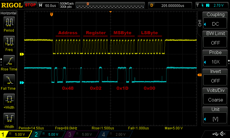
Now that we have the limits set, don’t forget to add setLimit(); to the setup section at the top of your code, we can focus on setting the fault tolerance limits. This is a little tricky, because we want to preserve the existing configuration and surgically change the value of the 11th and 12th bits. To accomplish this, we’ll use the technique of bit masking.
|
1 2 3 4 5 6 7 8 9 10 11 12 13 14 15 16 17 18 19 20 21 22 23 24 25 26 |
void setFaultTolerance() { int configValue = 0; Wire.beginTransmission (AT30TS750_I2C); Wire.write (REG_CONFIG); Wire.endTransmission (); Wire.requestFrom (AT30TS750_I2C, 1); configValue = Wire.read(); Wire.beginTransmission (AT30TS750_I2C); Wire.write (REG_CONFIG); Wire.write (configValue | 0x08); Wire.endTransmission (); // BEGIN DEBUG CODE Wire.beginTransmission (AT30TS750_I2C); Wire.write (REG_CONFIG); Wire.endTransmission (); Wire.requestFrom (AT30TS750_I2C, 1); configValue = Wire.read(); Serial.print ("CONFIG VALUE AFTER SETTING FAULT TOLERANCE: "); Serial.println (configValue, HEX); // END DEBUG CODE } |
Just above the debug code, there is the statement configValue | 0x08. configValue is loaded with the current configuration in the statement just above, and then here we take the existing configuration, and OR it with the value 0x08. This effectively writes our fault tolerance value into the configuration, leaving the existing values outside the fault tolerance bits untouched.
Since the default values of the entire configuration register are 0, and all we change in our init routine is to up the resolution by setting the 13-14 bits to 11, we can view the change we’re making like this…
|
1 2 3 4 |
B01100000 OR B00001000 ------------ B01101000 = 0x68 |
All you have to do is add setFaultTolerance(); to your setup and you can move on to interrupts!
Step Three: Interrupts
In order to successfully process an interrupt, we’ll need a couple of things.
- A function to call when we enter the alarm state
- A function to call when we exit the alarm state
- Some way of keeping track of our alarm state
For our AT30TS750A alarms functions, we can keep it simple and just call them AlarmOn and AlarmOff. Remember, the functions called by the interrupt have to be very quick, so the only thing we’re going to do in there is set the value of a variable.
That variable is the way we’re going to keep track of the alarm state. This is the special “volatile” variable we created in the definitions called alarmState. It’s going to have three states: 0, 1 and 2.
- If we’re in alarm state 0 then we just entered the alarm state and we have to do something about it.
- With alarm state 1 then we just exited the alarm state and we have to do something about it.
- Finally alarm state 2 indicates that we’ve processed either the entry or exit and we want our code to execute as usual.
You can see from the descriptions, that we should be spending the vast majority of our time in state 2. States 0 and 1 only come into play right when the interrupt has triggered or when it has released.
Ignoring all the other code in the sketch, we’ll isolate the interrupt code and describe it below…
|
1 2 3 4 5 6 7 8 9 10 11 12 13 14 15 16 17 18 19 20 21 22 23 24 25 26 27 28 29 30 31 32 33 34 35 36 |
volatile int alarmState = 0; // Alarm variable to be changed by the ISR. void setup() { interrupts(); // Turn on interrupt processing attachInterrupt (0, AlarmOn, FALLING); // When interrupt0 transitions from HIGH to LOW, execute the AlarmOn function alarmState = 3; } void loop() { if (alarmState == 0) TurnOffAlarmLights(); if (alarmState == 1) TurnOnAlarmLights (); } void AlarmOn() { alarmState = 1; } void AlarmOff() { alarmState = 0; } void TurnOnAlarmLights() { // CODE TO TURN ON LEDS attachInterrupt (0, AlarmOff, RISING); // When interrupt0 transitions from LOW to HIGH, execute the AlarmOff function alarmState = 2; } void TurnOffAlarmLights() { // CODE TO TURN OFF LEDS attachInterrupt (0, AlarmOn, FALLING); // When interrupt0 transitions from HIGH to LOW, execute the AlarmOn function alarmState = 2; } |
The attachInterrupt commands are how we tell the Arduino that we’re going to be listening to digital3 for interrupts full time. In this case we’re defining an interrupt as either FALLING or RISING. That means I am causing my code to key off the transition from one state to another, rather than the state itself. If you told the code to interrupt processing when the state was LOW instead of FALLING, then it would constantly trigger over and over and over again. We just want this to edge trigger so it hits once.
Our ISRs are nice and tidy. One line each, setting the global alarm state and that’s all. Once the alarm state has been set, it will be evaluated back in the main loop() and action is taken on it. When the alarm state is 1, we Turn On Alarm Lights. When alarm state is 0, we Turn Off Alarm Lights.
Inside each of the Alarm Light functions, we change the interrupt to trigger on the opposite value of whatever sent us in there to begin with. We do that because once we’re in the alarm state (caused by a falling edge on interrupt0), we need to now be ready for a RISING edge on interrupt0 to let us know that we’ve exited the alarm state. In each instance, we set the alarm state to the nice, calm, 2 at the end, to let our regular code processing continue.
So, if the temperature rises above Upper Limit, interrupt0 will drop from 5V to GND (the AT30TS750A alarms pin is open drain, so it’s default state is 5V, although that polarity can be changed in the configuration if you want to), triggering the FALLING state interrupt and launching AlarmOn, setting alarmState to 1. We reenter our loop and immediately process the IF statement evaluating alarmState, sending us to TurnOnAlarmLights. After taking action in there, we reset the alarmState to 2 and our code loops as usual, until the temperature drops below Lower Limit, in which case the RISING state of interrupt0 is detected, causing AlarmOff to be called, thus setting alarmState to 0 and causing us to turn our lights off and setup to listen for the interrupt triggering again on a FALLING edge.
Chances are, reading through the code makes more sense than my explanation 🙂
Step Four: Putting It All Together in an AT30TS750A Alarms Sketch
The good news, considering how long this module has gotten, is that the remaining code is all reusable from previous modules: GeneralCallReset and GetTemperature are nothing new. So you can put it all together and get this…
|
1 2 3 4 5 6 7 8 9 10 11 12 13 14 15 16 17 18 19 20 21 22 23 24 25 26 27 28 29 30 31 32 33 34 35 36 37 38 39 40 41 42 43 44 45 46 47 48 49 50 51 52 53 54 55 56 57 58 59 60 61 62 63 64 65 66 67 68 69 70 71 72 73 74 75 76 77 78 79 80 81 82 83 84 85 86 87 88 89 90 91 92 93 94 95 96 97 98 99 100 101 102 103 104 105 106 107 108 109 110 111 112 113 114 115 116 117 118 119 120 121 122 123 124 125 126 127 128 129 130 131 132 133 134 135 136 137 138 139 140 141 142 143 144 145 146 147 148 149 150 151 152 153 154 155 156 157 158 159 160 161 162 163 164 165 166 167 168 169 170 171 172 173 174 175 176 177 178 179 180 181 182 183 184 185 186 187 188 189 190 191 192 193 194 195 196 197 198 199 200 201 202 203 204 205 206 207 208 209 210 211 212 213 214 215 216 217 218 219 220 221 222 223 224 225 226 227 228 229 230 231 232 233 234 235 236 237 238 239 240 241 242 243 244 |
/* A sketch to use the temperature limit feature of the AT30TS750A on the Rheingold Heavy I2C and SPI Education Shield. Configuration: A. Temperature resolution = 9 bits B. Fault Tolerance = 2 measurements C. Upper Limit = startup temperature + 2 degrees C D. Lower Limit = startup temperature + 1 degrees C D. Alarm Mode = Comparator mode. F. DATA button = Read temperature. G. LATCH button = General call reset. Operation: 1. AT30TS750A powers up, samples the current temperature, adds two degrees to it and writes that to the upper limit register... adds one degree and writes that to the lower limit register. 2. AT30TS750A enters shutdown mode. 3. AT30TS750A issues a one shot measurement when the DATA button is pressed. 4. If two measurements exceed the upper limit, alarm is triggered. 5. Alarm is shown by all LEDs on the shift register turning on, and a serial print message. 6. Alarm remains on until temperature drops or General Call Reset is sent. Website: https://rheingoldheavy.com/at30ts750a-tutorial-alarms-limits-and-interrupts Datasheet: http://www.atmel.com/images/atmel-8855-dts-at30ts750a-datasheet.pdf */ #include "Wire.h" const int AT30TS750_I2C = 0x48; // I2C Address for the temperature sensor const int GENERALCALL_I2C = 0x00; // I2C General Call Address const byte REG_TEMP = 0x00; // Register Address: Temperature Value const byte REG_CONFIG = 0x01; // Register Address: Configuration const byte REG_LOWERLIMIT = 0x02; // Register Address: Lower Limit const byte REG_UPPERLIMIT = 0x03; // Register Address: Upper Limit const byte OPCODE_RESET = 0x06; // OPCode: Reset const int getTempButton = 8; // DATA button used for issuing one shot measurement const int resetButton = 7; // LATCH button used for general call reset const int dataPin = 8; // Variable used for controlling shift register const int latchPin = 7; // Variable used for controlling shift register const int clockPin = 6; // Variable used for controlling shift register const int oePin = 5; // Variable used for controlling shift register volatile int alarmState = 0; // Alarm variable to be changed by the ISR. void setup() { Serial.begin (9600); Wire.begin (); init_AT30TS750A (); //set general chip configurations pinMode (getTempButton, INPUT); pinMode (resetButton, INPUT); // configure our limit registers // configure fault tolerance // turn on interrupts // configure our interrupt to be ready for an alarm setLimits(); setFaultTolerance(); interrupts(); attachInterrupt (0, AlarmOn, FALLING); alarmState = 3; } void loop() { int buttonPressRead = 1; // Used to ensure our button press code only executes once per press int buttonPressReset = 1; // Used to ensure our button press code only executes once per press if (alarmState == 0) TurnOffAlarmLights(); if (alarmState == 1) TurnOnAlarmLights (); // When the DATA button is pressed, read the current temperature. while (digitalRead(getTempButton) == HIGH) { if (buttonPressRead == 1) { buttonPressRead = 0; grabTemperature (); } } // When the LATCH button is pressed, issue the General Call + Reset. while (digitalRead(resetButton) == HIGH) { if (buttonPressReset == 1) { buttonPressReset = 0; generalCallReset (); } } } void init_AT30TS750A() { /* Change the resolution of the temperature measurement * 0x00 = 9 bit resolution * 0x20 = 10 bit resolution * 0x40 = 11 bit resolution * 0x60 = 12 bit resolution */ Wire.beginTransmission (AT30TS750_I2C); Wire.write (REG_CONFIG); Wire.write (0x60); // Set Measurement Resolution Here Wire.endTransmission (); } void generalCallReset() { Serial.println (); Serial.println ("Issuing Power On Reset"); Serial.println (); Wire.beginTransmission (GENERALCALL_I2C); // Select the general call address Wire.write (OPCODE_RESET); // Write the reset opcode to any device listening Wire.endTransmission (); } void setFaultTolerance() { int configValue = 0; Wire.beginTransmission (AT30TS750_I2C); Wire.write (REG_CONFIG); Wire.endTransmission (); Wire.requestFrom (AT30TS750_I2C, 1); configValue = Wire.read(); Wire.beginTransmission (AT30TS750_I2C); Wire.write (REG_CONFIG); Wire.write (configValue | 0x08); Wire.endTransmission (); Wire.beginTransmission (AT30TS750_I2C); Wire.write (REG_CONFIG); Wire.endTransmission (); Wire.requestFrom (AT30TS750_I2C, 1); configValue = Wire.read(); Serial.print ("CONFIG VALUE AFTER SETTING FAULT TOLERANCE: "); Serial.println (configValue, HEX); } void setLimits() { byte tempMSByte = 0; Wire.beginTransmission (AT30TS750_I2C); Wire.write (REG_TEMP); Wire.endTransmission (); Wire.requestFrom (AT30TS750_I2C, 1); tempMSByte = Wire.read(); Serial.print ("tempMSByte in setLimits = "); Serial.println (tempMSByte, HEX); Serial.print ("tempMSByte + 0x01 in setLimits = "); Serial.println (tempMSByte + 0x01, HEX); Serial.print ("tempMSByte + 0x02 in setLimits = "); Serial.println (tempMSByte + 0x02, HEX); // The Limit Registers are 16 bits so you have to send 16 full bits // in this case, the second byte we're sending is just zeroes. Wire.beginTransmission (AT30TS750_I2C); Wire.write (REG_LOWERLIMIT); Wire.write (tempMSByte + 0x01); Wire.write (0x00); Wire.endTransmission (); Wire.beginTransmission (AT30TS750_I2C); Wire.write (REG_UPPERLIMIT); Wire.write (tempMSByte + 0x02); Wire.write (0x00); Wire.endTransmission (); } void grabTemperature() { byte tempLSByte = 0; byte tempMSByte = 0; float floatTemperature = 0.0000; Wire.beginTransmission (AT30TS750_I2C); Wire.write (REG_TEMP); Wire.endTransmission (); Wire.requestFrom (AT30TS750_I2C, 2); tempMSByte = Wire.read(); tempLSByte = Wire.read() >> 4; floatTemperature = tempMSByte + (tempLSByte * 0.0625); Serial.print ("The temperature is... "); Serial.print (floatTemperature, 4); Serial.print ("C, "); Serial.print ((floatTemperature * (1.8)) + 32, 4); Serial.println ("F"); } void AlarmOn() { alarmState = 1; } void AlarmOff() { alarmState = 0; } void TurnOnAlarmLights() { Serial.println ("ALARM TRIGGERED"); // Grab control of shift register pins briefly pinMode (latchPin, OUTPUT); pinMode (dataPin, OUTPUT); pinMode (clockPin, OUTPUT); pinMode (oePin, OUTPUT); // Turn on all LEDs digitalWrite (oePin, LOW); digitalWrite (latchPin, HIGH); shiftOut (dataPin, clockPin, MSBFIRST, 0xFF); digitalWrite (latchPin, LOW); // Release control of shift register pins back to buttons pinMode (getTempButton, INPUT); pinMode (resetButton, INPUT); attachInterrupt (0, AlarmOff, RISING); alarmState = 2; } void TurnOffAlarmLights() { Serial.println ("ALARM RELEASED"); digitalWrite (oePin, HIGH); attachInterrupt (0, AlarmOn, FALLING); alarmState = 2; } |
After compiling and uploading the code, open up the serial monitor. You should see some debug output there, showing the values of the temperature limits and the new configuration value. Press DATA a couple of times and you should see the current temperature displayed. Now, take something hot, even as simple as rubbing your finger against your pants or the mousepad on your desk a couple of times to get the tip nice and warm and press it against the AT30TS750A on the Education Shield for a few seconds. If you can raise the temperature by two degrees that way you should see the LEDs pop on. Then, if you blow across the sensor gently to cool it off, the LEDs should turn off. There is corresponding debug code that appears in the serial monitor as well when both states execute.
The AT30TS750A packaging is very sturdy and robust, considering that it’s expecting to be either touched by a soldering iron or placed in a reflow oven. If you have trouble getting the chip to trigger or release the alarm, set the upper and lower limits 10 or 15 degrees higher, and use a hair dryer or something like that to create the sudden temperature increase.
