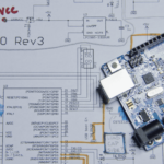
Welcome to the Rheingold Heavy I2C Display Add-on v2. This circuit board is designed to work as an independent display capable of helping you to visualize data that you’re receiving from sensors. It works exceptionally well with the I2C and SPI Education Shield and the components of the Breakout Bundle.
Objectives
- Understand the various operating characteristics of the I2C Display Add-on.
- Understand what the connection requirements are for compatibility with various microcontrollers.
- Identify the different subsystems on the board.
- Understand how to connect the display to your microcontroller.
Background
I2C Display Add-on v2 Product Page
Lite-On Seven Segment Display Datasheet
Cree RGB LED Datasheet
IS31FL3728 Datasheet
Setup
There is no setup required for this module.
I2C Display Add-on Operating Characteristics
The I2C Display Add-on is designed to work with any 5V I2C compatible microcontroller, with the Arduino UNO specifically used during development. The main IC, the ISSI IS31FL3728 is able to run at 3V3, however the LEDs were selected with 5V VCC in mind, and the reduced voltage would consequently result in a significantly lower maximum brightness. No harm would come to the device by doing so however.
| Measurement | Vs Measured | Vf Measured | R Measured | I Measured | I Calculated |
|---|---|---|---|---|---|
| 220Ω | 4.88 | 1.95 | 217 | 0.0130 | 0.0135 |
| 470Ω | 4.88 | 1.89 | 457 | 0.0064 | 0.0065 |
| 2200Ω | 4.88 | 1.79 | 2140 | 0.0014 | 0.0014 |
| 10K | 4.88 | 1.72 | 10010 | 0.0003 | 0.0003 |
*Values published in respective manufacturer’s datasheet.
**Min value with Intensity = 0x08, Max value with Intensity = 0x07. Current measured at 5V pin of display.
Pin Out
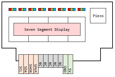
The “NC” labeled pins are “not connected” on the PCB. Those positions are only there so that they can be used to provide mechanical stability, if necessary, when connecting the display to a breadboard or perfboard.
Visual Guide
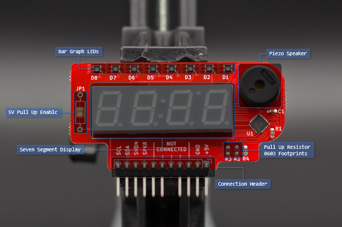
Subsystem Description
Display Driver
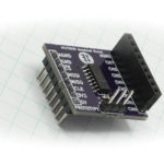
The heart of the I2C Display is the IS31FL3728 LED driver chip manufactured by ISSI. It controls the output of all the portions of the display using I2C communications by way of the connection header. The board is designed to allow the IS31FL3728 to manage the forward voltage requirements and maximum current driven to any portion of the display.
The I2C bus on the Display does not have pull up resistors soldered to it, however the R2 and R3 pads are available for use with 0603 sized SMD resistors. It is highly recommended that you use correctly sized external pull up resistors, however the internal pull up resistors of your microcontroller may work as well. For the Arduino Uno, using the I2C library linked here, you can very easily enable the internal pull ups.
Shutdown Pin
The shutdown pin of the IS31FL3728 is broken out at the connection header for ease of use. It is active LOW, so make sure you configure it’s connected pin on your microcontroller as an OUTPUT and drive that pin HIGH in order to get the display to turn on. Using the shutdown pin causes the current consumption of the display driver to drop below 1mA, so for a battery operated installation, it is recommended to use the shutdown rather than simply blanking the display by writing zeros to the column registers.
Seven Segment Display
The four digit, seven segment display is connected to the IS31FL3728 on the PCB directly. The display is a common cathode configuration featuring four discrete digits, associated decimal place LEDs and three additional LEDs that arranged as the colon delimiter in a clock display, with the third LED existing for reasons that are beyond me, but it’s there if you want to use it (it was suggested to me by customer Robert, that this third LED is very useful as a “degree symbol” indicator). The three additional LEDs are designated as L1, L2, and L3 in the datasheet.
LED Bar Graph
The LED Bar Graph consists of eight Red / Green / Blue (RGB) LEDs. Each color pixel for each LED can be turned on individually or in groups with all three colors being used simultaneously if desired. Limited color mixing is easily performed through combinations of the each color at full brightness, and further advanced color mixing can be performed by adjusting the brightness by color.
LED Register Addresses
The IS31FL3728 datasheet refers to registers used to control the LEDs by their “Column”, rather than digits, however, that is only important for the circuit design, and you can think of the columns mentioned in the datasheet as digits if you find it helpful.
- The red RGB row is connected to the IS31FL3728 as digit 0.
- The green RGB row is connected to the IS31FL3728 as digit 1.
- The blue RGB rowis connected to the IS31FL3728 as digit 2.
- The extra L1/L2/L3 LEDs are connected to the IS31FL3728 as digit 3.
- The digits of the display are connected to the IS31FL3728 as digits 7, 6, 5 and 4, from left to right.
Piezo Speaker
A Piezo speaker is available to use as a buzzer or simple tone player in the upper right hand corner of the display. It is controlled through the SPKR pin on the connection header.
Connection
The connection of the display is designed for use with either the included right angled pin headers, or any other form of 0.1″ pin pitch header you wish to use. The pinout of the Display is designed to mate directly with any Arduino UNO or UNO compatible shield, by using a right angle connector and matching the 5V and GND pins.
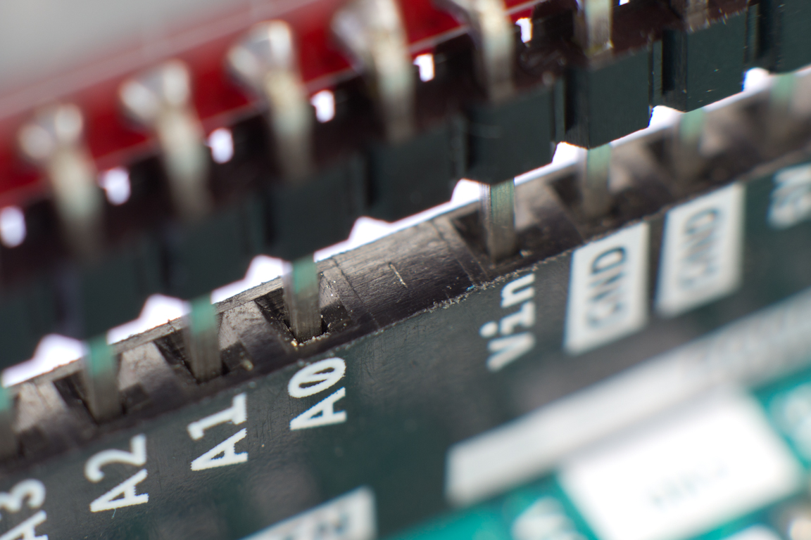
On newer version of the UNO boards, the manufacturers started installing a single straight header along the analog header side of the board, with the single unused space containing a filled blank. If that is the case, you can either clip off the pin from a currently soldered header, or snap a header into two pieces of 6 and 4 pins each to solder into place, leaving a space at that middle position.
For more I2C Display tutorials, Click Here.