In the last module, we went from using massive chunks of code to flip individual bits, to a more elegant solution that replicated the ability of the built-in shiftOut() function. Now we’ll use the tools from the previous module to expand our abilities to modify the individual values contained in a byte.
Objectives
- Understand what the term bit masking means.
- Continued practice using bitwise operators.
- Be able to set, clear or retrieve individual bits from an 8-bit variable.
Background
Bit Shifting the 74HC595
Boolean and Bitwise Operators
Schematic
Education Shield – Shift Register Subsystem
Setup
For this module, you’ll need the following equipment:
- Education Shield or the Manual Serial Communications Trainer
- Arduino UNO R3
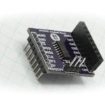
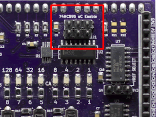
1. Place jumpers on the 74HC595 Enable block along the edge of the Education Shield. This will enable microcontroller interaction with the shift register.
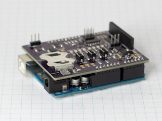
2. Mate the Education Shield with your Arduino UNO R3.
3. Finally, connect your Arduino to your USB cable, and upload this little sketch to drive the OE pin low.
|
1 2 3 4 5 6 7 |
void setup() { int oePin = 5; pinMode (oePin, OUTPUT); digitalWrite (oePin, LOW); } void loop() {} |
Alternatively, you can use the Manual Serial Communications Trainer instead. Connect 5V and CLR to 5V, GND and OE to GND, DATA to D8, LATCH to D7, and CLOCK to D6. The code above is not necessary in this configuration.
Bit Masking
Every chip you will use with serial communications will need configuration, and in some cases, the datasheet will show that various portions of the data stream, either sent or received, need to be ignored. The method used to process this is called bit masking. Bit masking is a way to modify or isolate the contents of a chunk of data in a way that ensures the rest of the data remains unaltered. It’s called a mask because it functions in the same way you use masking tape when you paint a wall — the tape isolates the paint to a specific area of operation. That is a key point: your work within a configuration register, or manipulation of a data stream needs to be surgical in nature — go in, change a bit, get out.
To implement this, we’ll make repeated use of the boolean and bitwise operators discussed previously. I’ll also present the information in both binary, which is much easier to understand intuitively but only available in the Arduino IDE, and hex which is used commonly and available universally. Also note, that the bits are counted from the 0th bit to the 7th, right to left, not from the 1st to the 8th.
Problem: The data sheet says that in order to turn the chip functionality on, we have to enable the sixth bit. The other seven bits are factory configured, not described and should not be changed. This is a common configuration method for a chip that has a power save feature.
So, we have something that looks like Bx0xxxxxx. We need to change the 0 to a 1, and we need to make sure that none of the other bits are changed. If you look at the surgical tools of bit operation, you’ll see the and, or, xor and not. Rather than detail the various truth tables again, let’s think of how each of those works in plain English.
If you compare a value with and, it will set everything to zero, unless you have a one in both places. That sounds like it would be good for blanking things out since it makes it really easy to create zeros.
If you compare a value with or, it will set everything to one, unless you have a zero in both places. That sounds like it would be good for enabling things since it makes it really easy to create ones.
If you compare a value with xor, it will flip anything that doesn’t match from the original to its opposite, but leave anything that does match the same.
not isn’t a comparison, it’s just a hammer for very specific nails, taking the entire set of data you give it and flipping each bit to its opposite.
It sounds like using the or bitwise operator will be of best use here, since we can use it to leave the original values the same except for the single 1 we want to ensure is a 1. We do this by passing in a bunch of zeros. If there is a zero in the original byte, it will still be a zero after applying our test, because 0|0 = 0. If there is a one in the original byte, it will still be a one after applying our test, because 1|0 = 1. On the sixth bit though, we will put a one in our test. That will force a one into our result because 0|1 = 1.
|
1 2 3 4 |
Bx0xxxxxx OR B01000000 --------- Bx1xxxxxx |
Remember, the datasheet doesn’t say what the original values of those bits are. We could sample them with an oscilloscope or a logic analyzer if we cared to, but they will only tell us what they are, not what they’re used for… that’s a secret known only to the manufacturer. But in this case, we will just treat it like a black box and enable our bit. Here’s how we would do it in code.
|
1 2 |
thingWeWantToChange = valueInFromChip; thingWeWantToChange = thingWeWantToChange | B01000000; |
Again, the binary values only apply to writing code in the Arduino IDE, so to adhere more closely to how other code is written, let’s use hex instead: B01000000 = 0x40
|
1 2 |
thingWeWantToChange = valueInFromChip; thingWeWantToChange = thingWeWantToChange | 0x40; |
This code can be optimized further…
|
1 |
thingWeWantToChange = valueInFromChip | 0x40; |
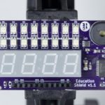
Here is a sketch you can use to visualize the bit mask by sending the values to the shift register so they can be displayed on the LEDs of the Education Shield…
|
1 2 3 4 5 6 7 8 9 10 11 12 13 14 15 16 17 18 19 20 21 22 23 24 25 26 27 28 29 30 31 32 33 34 35 36 37 38 39 40 41 42 43 44 45 46 47 48 49 50 51 52 53 54 55 56 57 58 59 60 61 62 63 64 65 66 67 68 69 70 71 72 |
/* Bit Masking the 74HC595. Example 1. https://rheingoldheavy.com/bit-masking-74hc595 */ // Set the pin connections from the shift register int dataPin = 8; int latchPin = 7; int clockPin = 6; int oePin = 5; void setup() { // Set the pin modes for our clock, data and latch pins to output. pinMode(latchPin, OUTPUT); pinMode(dataPin, OUTPUT); pinMode(clockPin, OUTPUT); pinMode(oePin, OUTPUT); // Enable all the outputs of the shift register. digitalWrite (oePin, LOW); } void loop() { byte originalValue = 0x16; // This is the byte that we are going to squeeze through the mask (equiv. B00010100) byte mask = 0x40; // The bit mask we'll be ORing (equiv. B01000000) byte newValue = 0; // A byte variable to hold the results of our mask process, initialized to 0 int i = 0; // this will be used in the for loop below newValue = originalValue | mask; // Display the original value refreshShiftRegister(originalValue); delay(2500); // Flash the bits that are going to be masked three times for (i = 0; i < 3; i++) { refreshShiftRegister(newValue); delay(250); refreshShiftRegister(originalValue); delay(250); } // Display the new value refreshShiftRegister(newValue); delay(2500); // Clear the register before looping refreshShiftRegister(0); delay(500); } // This function performs our manipulation of the shift register in order to display a byte of data // It accepts a byte variable called "input" that is used by shiftOut() to create the LED pattern // The function manages the process of sending the data to the shift register and then cycling the latch pin void refreshShiftRegister(byte input) { digitalWrite (latchPin, LOW); shiftOut (dataPin, clockPin, LSBFIRST, input); digitalWrite (latchPin, HIGH); } |
Problem: We have a chip that does on-board processing of data. It lets us know that the processing is finished and the data is available by enabling a data ready bit, which, for reasons known only to the manufacturer, is the 3rd bit inside 8-bits of unrelated data that we need to ignore.
What we need to do is isolate the data ready bit, determine if it’s a one or a zero and then take action based on the result. If we tried using the method from the first problem, we would create a bug because using the or operator would result in all the other bits retaining their value, and a one always being placed in the position we’re checking. We need to blank out the rest of the byte so that the state of this individual bit stands out. That means we need to create a bunch of zeros, and to do that, the and operator is our friend. We are going to and the incoming data with the value B00001000. If a bit in the original value is a zero, then our mask will return a zero, because 0&0 = 0. If a bit in the original value is a one, then our mask will return a zero as well, because 1&0=0. On the third bit though, we will retrieve the bit in the original value: if it’s a one, then 1&1=1, and if it’s a zero, then 0&1=0.
|
1 2 3 4 |
Bxxxx?xxx AND B00001000 --------- B0000?000 |
Again, we’re treating the unrelated bits as black boxes, we don’t know what they are, and we don’t care at this point, we just need to eliminate them so we can test to see if the data is ready for processing. Here is how it would look in code…
|
1 2 |
isDataReady = valueInFromChip; isDataReady = isDataReady & B00001000; |
… and here it is with hex: B00001000 = 0x08
|
1 2 |
isDataReady = valueInFromChip; isDataReady = isDataReady & 0x08; |
This code can also be optimized further…
|
1 |
isDataReady = valueInFromChip & 0x08; |
To pull the curtain back a little further on this example, realize that if the data isn’t ready, the masked isDataReady value will equal zero. However, after the processing has occurred and the data ready bit has been flipped, the masked isDataReady value will equal 0x08. You can treat that as either the actual value or simply as a non-zero value to test. Typically, you would grab the masked isDataReady value from a function that does the actual serial communication and masking, and then use it in a polling algorithm, either testing with an if statement, or more likely, putting yourself in a holding pattern with a do…while loop waiting for the processing to complete. Here’s some psuedocode to illustrate the do…while loop example.
|
1 2 3 |
do { isDataReady = getIsDataReadyBit; } while isDataReady = 0x00; |
And here is some visualization code…
|
1 2 3 4 5 6 7 8 9 10 11 12 13 14 15 16 17 18 19 20 21 22 23 24 25 26 27 28 29 30 31 32 33 34 35 36 37 38 39 40 41 42 43 44 45 46 47 48 49 50 51 52 53 54 55 56 57 58 59 60 61 62 63 64 65 66 67 68 69 70 71 72 73 74 75 76 77 78 79 80 81 82 83 84 85 86 87 88 89 90 91 92 |
/* Bit Masking the 74HC595. Example 2. https://rheingoldheavy.com/bit-masking-74hc595 */ // Set the pin connections from the shift register int dataPin = 8; int latchPin = 7; int clockPin = 6; int oePin = 5; void setup() { // Set the initial pin modes for our clock, data and latch pins to output. pinMode(latchPin, OUTPUT); pinMode(dataPin, OUTPUT); pinMode(clockPin, OUTPUT); pinMode(oePin, OUTPUT); // Enable all the shift register outputs. digitalWrite (oePin, LOW); Serial.begin (9600); } void loop() { byte originalValue = 0xC7; // This is the byte that we are going to squeeze through the mask (equiv. B11000111) byte mask = 0x20; // The bit mask we'll be ANDing (equiv. B00100000) byte bitTest = 0; // A byte variable to hold the results of our mask process, initialized to 0 int i = 0; // this will be used in the for loop below // Display the original value refreshShiftRegister(originalValue); // This loop changes the latchPin to an input, so that it can be used to simulate a chip setting the DATAREADY bit do { pinMode (latchPin, INPUT); Serial.print ("latchPin value: "); Serial.println (digitalRead(latchPin)); originalValue = originalValue | digitalRead(latchPin) << 5; // shift the state of the latchPin into the DATAREADY bit position bitTest = originalValue & mask; // use the mask to determine if the DATAREADY bit is set pinMode (latchPin, OUTPUT); Serial.print ("originalValue: 0x"); Serial.println (originalValue, HEX); Serial.print ("Mask: 0x"); Serial.println (mask, HEX); Serial.print ("originalValue & mask: 0x"); Serial.println (bitTest, HEX); Serial.println (); } while (bitTest == 0); // If the DATAREADY bit is not set, bitTest = 0, if DATAREADY is set, bitTest = 0x20 // Flash the bits that are going to be masked three times for (i = 0; i < 3; i++) { refreshShiftRegister(originalValue & ~mask); delay(250); refreshShiftRegister(originalValue); delay(250); } // Display the new value refreshShiftRegister(bitTest); delay(2500); // Clear the register before looping refreshShiftRegister(0); delay(500); } // This function performs our manipulation of the shift register in order to display a byte of data // It accepts a byte variable called "input" that is used by shiftOut() to create the LED pattern // The function manages the process of sending the data to the shift register and then cycling the latch pin void refreshShiftRegister(byte input) { digitalWrite (latchPin, LOW); shiftOut (dataPin, clockPin, LSBFIRST, input); digitalWrite (latchPin, HIGH); } |
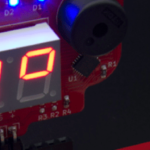
In the example code above, the LATCH button on the Education Shield is used to simulate a chip setting the DATAREADY bit. When the LATCH button is pressed, the value of the latchPin is shifted into the dataready bit position to be tested by the mask. When the change is detected in the DO…WHILE loop, the original value of the byte is flashed with the mask to show you which bit is being tested, and then shows the end result after masking, before looping to the start.
In the DO…WHILE loop, you will see the pinMode of latchPin flipped to an input state, and then after these two lines, the latchPin is immediately changed back to an OUTPUT. One of the limitations of the Education Shield is that the buttons are directly connected to pins which are also connected via jumpers to the 74HC595, so while you’re using the shift register, the buttons could potentially interfere with the functioning of the code. I use the LATCH button because it has no affect on the shift register unless data is in the process of being transferred. Since my control code in the DO…WHILE loop isn’t clocking in data, I can quickly utilize the debounced LATCH button as an input, as long as I turn it back to an output before data is clocked. This can be used as a handy work around for any code you may want to use in the future.
There is a large section of serial debug output that can help you to see the values as they are changed.
In the example code where the masked bits are flashed three times, you see the following:
|
1 |
refreshShiftRegister(originalValue & ~mask); |
Why does the mask have the not bitwise operator applied to it and what is the affect?
Hover to read answer
Bxxx00001 = COLD
Bxxx00011 = WARM
Bxxx00111 = HOT
Bxxx01111 = VERY HOT
Bxxx11111 = HOLY HELL
B001xxxxx = COMPLETELY CLOSED
Bx11xxxxx = HALF OPEN
B111xxxxx = COMPLETELY OPEN
Let’s call the tap control bits “C” and the temperature value bits “T”. The byte we get back would look like this: BCCCTTTTT. When we retrieve the data, our temperature value needs to be isolated from the control value or we’ll get crazy readings, and since it makes sense that the configuration of the tap would be based on the temperature, we need to make sure that we don’t mess with the temperature bits when we set the tap bits.
Let’s rewrite the byte map in hex to show concrete values for the various levels. It will be the goal of our code to replace all the x’s with zeros.
0x01 = COLD
0x03 = WARM
0x07 = HOT
0x0F = VERY HOT
0x1F = HOLY HELL
0x20 = COMPLETELY CLOSED
0x60 = HALF OPEN
0xE0 = COMPLETELY OPEN
So let’s assume we have a two variables, one called currentTemp that will hold the water temperature and tapConfig that will hold the tap configuration we want to send to the chip, and we have two functions, getData pulls the byte from the chip and setTap(tapConfig), sends the byte back to the chip.
What code would you use to retrieve and isolate the current temperature?
What code could you use to set the tap to completely closed?
Problem: You have a 24 bit ADC, but your serial communications method is only able to transfer 8 bits at a time. The datasheet goes on to say that the values are sent least significant byte first. How do you assemble a complete and accurate value for each reading when your data is only sent in chunks.
The first thing to note is the data width of our ADC value: 24 bits. Immediately, we know that we can’t store a 24 bit value in a byte (1 byte = 8 bits), and an integer variable is 16 bits, so still too small. You have to go to a long, capable of holding a 32 bit value, in order to accept the full value from the ADC. We’ll create a long called fullValue to hold our ADC reading.
|
1 |
long fullValue = 0; |
So now we have a place to put the data, but we need to load it into the variable in the correct sequence. Let’s assume that there’s a function, getADCdata() that performs the serial interchange and returns our data to us in three bytes (3 x 1 byte = 24 bits = ADC reading), but in the sequence described in the datasheet. Those three bytes are called adcLeastSigByte , adcMidSigByte and adcMostSigByte .
|
1 2 3 4 5 6 7 |
byte adcLeastSigByte = 0; byte adcMidSigByte = 0; byte adcMostSigByte = 0; adcLeastSigByte = getADCdata(); adcMidSigByte = getADCdata(); adcMostSigByte = getADCdata(); |
By using a combination of bit shifting and oring, we can assemble our long from the three component parts.
We’ll use the following example values…
|
1 2 3 4 |
fullValue = B0000 0000 0000 0000 0000 0000 0000 0000 adcLeastSigByte = B11111111 adcMidSigByte = B01011010 adcMostSigByte = B00000110 |
What you do is take the Most Significant Byte and shift it to the left 16 bits, then take the Middle Significant Byte and shift it over 8 and finally tack the Least Significant Byte onto the end. Each chunk shifted to the left is ored with the next incoming value…
fullValue = ((adcMostSigByte << 16) | (adcMidSigByte << 8) | (adcLeastSigByte) );That code essentially performs the following…
|
1 2 3 4 5 6 7 8 9 10 |
0000 0000 0000 0000 0000 0000 0000 0000 OR 0000 0110 <<<< <<<< <<<< <<<< ------------------------------------------- 0000 0000 0000 0110 0000 0000 0000 0000 OR 0101 1010 <<<< <<<< ------------------------------------------- 0000 0000 0000 0110 0101 1010 0000 0000 OR 1111 1111 ------------------------------------------- 0000 0000 0000 0110 0101 1010 1111 1111 |
If the most significant bit of the 24 bits returned was a validation bit indicating that the ADC was ready to perform another sample, how would you isolate that bit to test?