In this tutorial, we’ll start to explore how to interact with the I2C Display Add-on using the I2C interface of an Arduino. The Display features a four digit seven-segment display as well as a bar graphs made with red / green / blue LEDs all driven by an Lumissil IS31FL3728 LED Driver. The register map for the driver isn’t terribly complex, so you should be able to get up and running with the display in short order!
Background
I2C Basics
Changing the I2C Library
IS31FL3728 Datasheet
I2C Display Setup
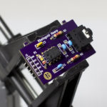
The Display only requires six connections: 5V, GND, SCL, SDA as well as a connection for the shutdown pin and the piezo speaker. It was designed to work directly with the I2C and SPI Education Shield, and because of that, it does not have I2C pull up resistors on board. Depending on what you’re connecting to, it may be necessary to provide those resistors, or to configure the I2C pins you use to use internal pull up resistors. For general connections to an Arduino or other development board, pull up resistors of 4.7K should be sufficient.
IS31FL3728 LED Driver Overview
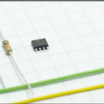
The brains of the I2C Display is the ISSI IS31FL3728 LED driver, and it provides all the LED power and signal processing necessary to turn the LEDs on and off. The v1 edition of the board used the AMS AS1115 LED Driver chip, which had some built in decoding that could be used to easily output the numeric characters to a seven segment display. The ISSI chip doesn’t do that, but by adding a few lines of code to your sketch, it’s easy enough to create your own function to accomplish the same thing.
Configuration Register
The chip is configured for operation by using the Configuration Register at address 0x00. There are three sections that comprise that register:
- Bits 0-1 = Array Mode Selection
- Bit 2 = Audio Input Enable (audio features not implemented)
- Bits 3-6 = RESERVED
- Bit 7 = Software Shutdown
The I2C Display Add-on v2 is designed as an 8×8 matrix, so the Array Mode Selection bits should be configured as 00. The display does not implement the audio input features of the IS31FL3728, so the Audio Input Enable bit should be 0. We want the display to turn on, so the software shutdown bit should be 0 (more information on software shutdown below). The reserved bits we don’t care about, so you can write them to 0000 as well.
That means, in order to correctly configure the chip to turn the display on, you just need to send the value of 0x00 to the 0x00 register address! Super simple!
Digit Register
The primary design of the chip is to control matrixes of LEDs connected in a multiplexed pattern, in this case a matrix of 8 rows and 8 columns, where all the anodes of a row, and all the cathodes of a column are connected. The seven segment display isn’t a conventional display matrix, but the way it’s been designed allows it to be controlled in exactly the same manner. Each digit of the display is comprised of seven LED “segments” as well as a decimal place, and then those eight LEDs are configured (and referenced) in this pattern…

The banks of LEDs that make up the digits and the RGB bar graph are referenced in the datasheet as Column 0 through Column 7, with corresponding register addresses of 0x01 through 0x08.
Column Update Register
Writing bit values to the Digit Registers only updates an internal buffer within the ISSI chip. In order to latch those changes to the display, you need to write some value to the Column Update Register. That value can be any 8 bit number, so I generally use 0xCC as a dummy value to send. The data sent doesn’t matter, it’s the act of sending the data that causes the display to be updated.
Brightness and Intensity
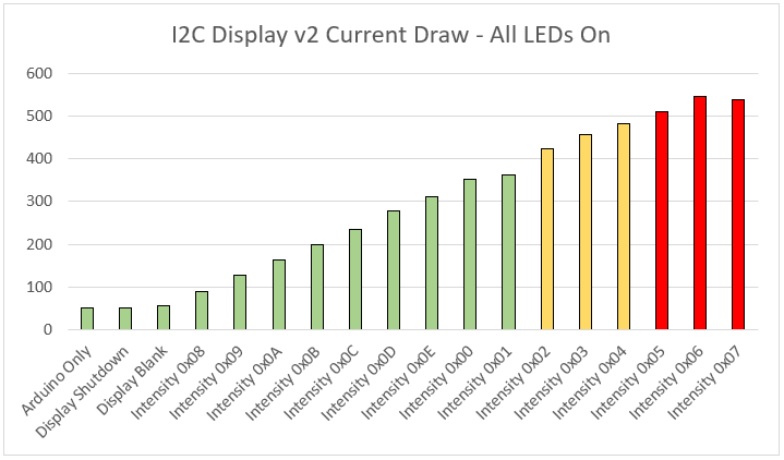
The brightness (called intensity in the datasheet) of the display as a whole is controlled using the Lighting Effect Register 0x0D. Changing the values of that register allows a larger amount of current to be drawn by the display through the ISSI chip, called the “Current Setting” in the datasheet. There are 15 brightness levels however they are oddly sequenced, with 0x08 being dimmest, growing in intensity through 0x0E, then growing further from 0x00 to the highest intensity at level 0x07. Obviously how “bright”, bright actually is will be entirely subjective, so you’ll have to play around with it to determine what’s best for the environment you’re using the display in.
If you are connecting the display so that is powered from the 5V pin of the Arduino, you have to be mindful of the amount of current drawn. First, be careful not to exceed the maximum suggested current draw of 500mA. See the chart below for current draw versus intensity settings with all the LEDs enabled. Second, the LEDs themselves have maximum current values as well, 70/50/50 mA for the R/G/B and 90mA for the segments of the digits. Those are maximum values however, with their prefered current levels much lower. See the datasheets for the LEDs for more detail, but generally, set the brightness to the value of 8, 9 or 10 to be completely safe.
You set the global brightness by applying the 8-14/0-7 value to the 0x0D register. Those are written to bits 0-4 of the “Lighting Effect Register”, and the remaining bits won’t have any effect because they are for a feature not implemented on the Display. Individual LED brightness is not realistically achievable as the refresh rate performed by the ISSI chip and the timing of the code sequence you would need to rewrite the brightness and update the display for those individual LEDs eventually comes into conflict and causes flickering and brightness bursts or drop outs.
Software and Hardware Shutdown
There are two ways to achieve a shutdown of the IS31FL3728 LED Driver. Both methods allow you to instantly disable the display without wiping the current values / patterns displayed: all registers retain their values in shutdown.
The first method is by using the SHUTDOWN pin, connected to Arduino pin A3. The SHUTDOWN pin is active low, so to enable the display, digitalWrite() the pin high, and to disable the display set it low.
The second method is by using the Sofware Shutdown bit in the Configuration register. Writing a 1 to bit 7 of the configuration register enables Software Shutdown Mode, and writing a 0 exists shutdown. The end result is the same regardless of which method you choose.
The act of being in shutdown takes precedent so both the software and hardware states need to be out of shutdown for the chip to function.
For more I2C Display tutorials, Click Here.