Welcome to your new MSGEQ7 Breakout Board Kit! The components for the kit and the spacing on the PCB were both designed to make this as easy to assemble as possible. With a little bit of time and solder, you’ll have a fully working seven frequency band graphic equalizer to play with.
Parts List
Double check your package to make sure you have the following parts…
| Reference Designator | Part Description |
|---|---|
| PCB | MSGEQ7 Breakout Board Printed Circuit Board |
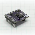
| U1 | Mixed Signal Integration MSGEQ7 Integrated Circuit |
| J1 | 5 Pin Header |
| J2 | 3.5mm Stereo Jack |
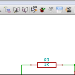
| R1 | 200K Resistor |
| R2, R3 | 22K Resistor (2x) |
| C1, C2, C4 | 0.1uF Capacitor (3x) |
| C3 | 33pF Capacitor |
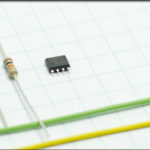
The parts look like this…

Assembly Instructions
- Start by laying out the parts so you can clearly see each component. Fortunately, the quantities are unique, so it should make it easy to figure out which part matches with with reference designator. If you’ve already separated them from the tape and aren’t certain what’s what, the 22K Resistor has ORA-ORA-RED color bands, the 200K Resistor has ORA-BLK-RED color bands, the 33pF capacitor is labeled “33” and the 0.1uF capacitor is labeled “104”.
- Solder the integrated circuit down first. As with most DIP packages, you’ll need to bend the pins closer to 90 degrees to the body of the component first, to get it to align with the footprint on the PCB. The Pin 1 marking is the circle on the top of the case and should be placed lower left when looking directly at the face of the PCB.
- Once U1 is on the board, work your way outwards, one component at a time. R1, C1, C4, C3, then C2, R2, R3. After you solder each component, visually inspect it to make sure you don’t have a cold solder joint, then trim the leads before continuing on to the next.
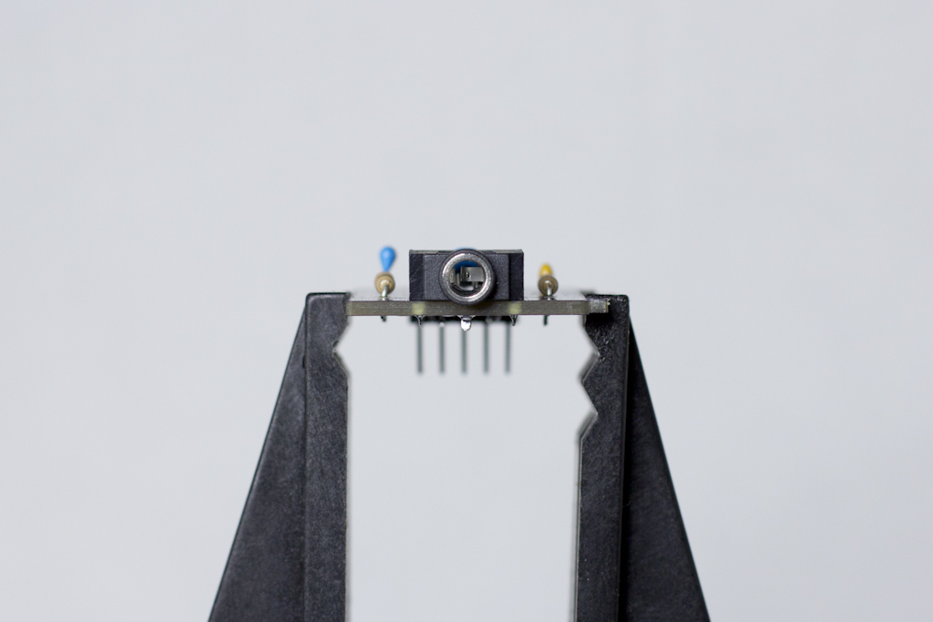
- Soldering J2, the 3.5mm Stereo Jack may seem a little tricky, because the holes have to be quite large for the flat spade pins to fit in (the PCB fab can’t make oval holes). Make sure the body is laying flat against the PCB, because of the very tight tolerances, it might get a little hung up right at the edge, but a little wiggling will have it fit securely. When you start to solder, don’t be shy… flood each of the positions with solder until you have a complete joint. Don’t try to simply take it to the place it looks like it’s touching. The plastic of the body is high temperature resistant, so you won’t melt it if the solder flows the PCB.
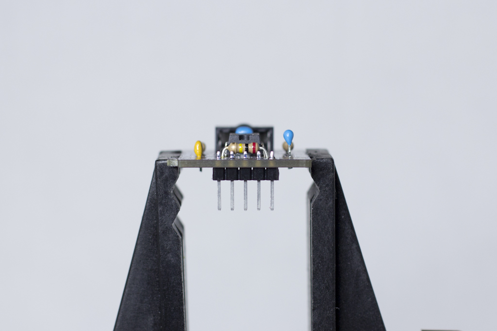
- Solder the five pin header on, with the long end of the pins under the board, and the short end of the pins sticking through the board.
That’s all there is to it! Just go slow and use a good soldering iron, and you shouldn’t have any problems at all.
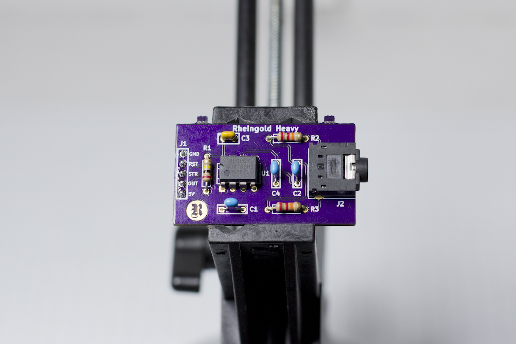
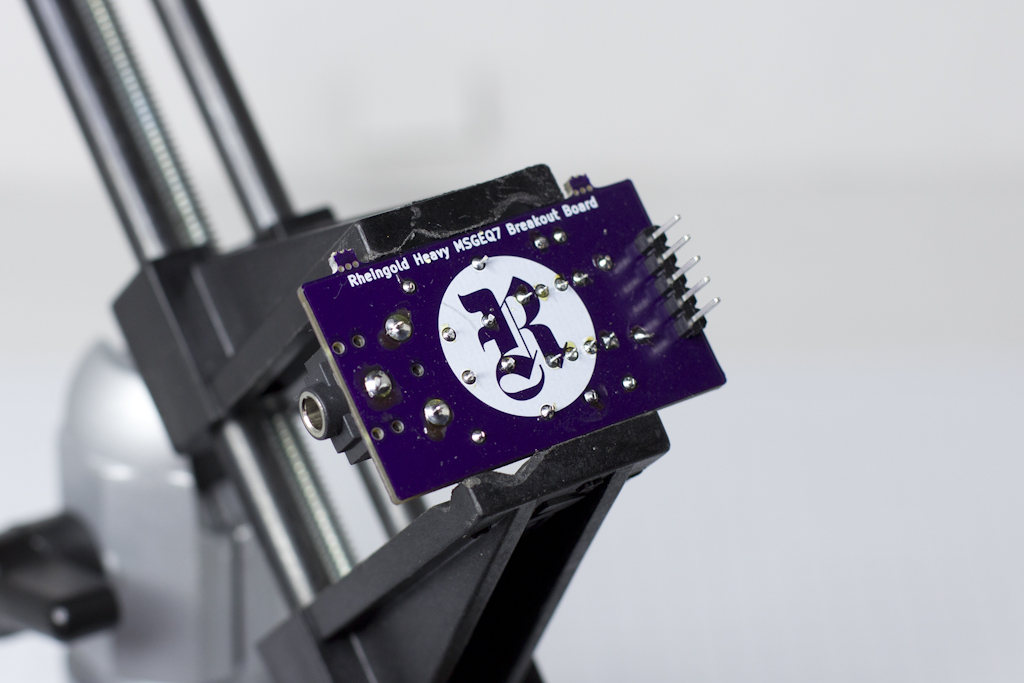
Reference Assembly
This is what it looks like completely assembled.

If you have any issues, send an email to support@rheingoldheavy.com.