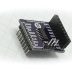
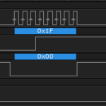
The I2C and SPI Education Shield features two devices on the I2C bus, the MCP7940 and AT30TS750A chips, a real time clock and temperature sensor respectively. Let’s combine the two and retrieve the temperature along side a time stamp.
Objectives
- Learn how to check for and handle errors.
- Understand the error codes that can be returned.
- Define the registers necessary to utilize both modules.
- Retrieve data from both devices in the shortest time possible.
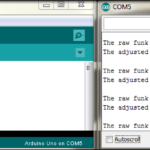
- Send the output to the serial window.
Background
MCP7940 Functionality Overview
AT30TS750A Functionality Overview
Microchip MCP7940 RTC Datasheet
Atmel AT30TS750A Temperature Sensor Datasheet
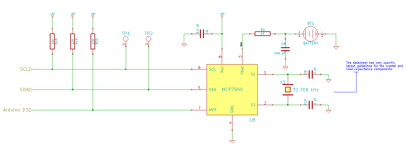
Schematic
Education Shield – MCP7940 RTCC Subsystem
Education Shield – AT30TS750A Temperature Sensor Subsystem
Setup
For this module, you’ll need the following equipment:
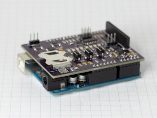
- I2C and SPI Education Shield or the MCP7940 Breakout Board and the AT30TS750A Breakout Board
- Arduino UNO R3
1. Insert a CR2032 button cell battery in the battery holder on the edge of the Education Shield. It should be placed positive side up.
2. Mate the Education Shield with your Arduino UNO R3. If you’re using the MCP7940 Breakout Board with the AT30TS750A Breakout Board, for each board connect 5V to 5V, GND to GND, SCL to Analog 5, and SDA to Analog 4. The MFP pin on the MCP7940 connects to Digital3, and AL on the AT30TS750A connects to Digital2.
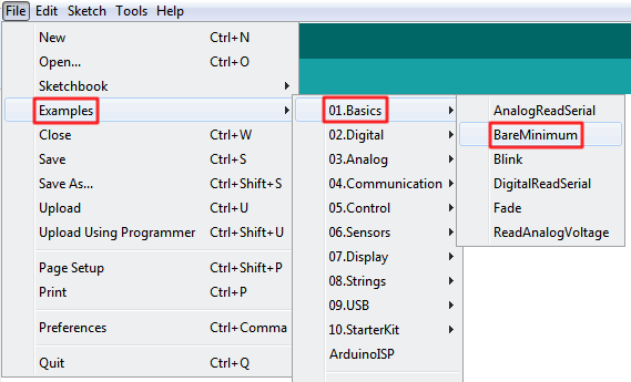
3. Connect your Arduino to your USB cable, and use the Arduino IDE to upload the “Bare Minimum” sketch from the Basics section of the Examples.
Arduino I2C Errors
Our architecture presents a single master on the I2C bus and multiple I2C devices, that means we’ll only be able to interact with a single device at a time, but nothing prevents us from interacting with the two devices rapidly in sequence. Provided the bus is allowed to return to the free state in between interactions, data can flow back and forth without issue from different sensors to the master.
Fortunately, the I2C library (and the original Wire library as well) handle establishing the free state on our behalf, meaning we don’t have to do anything very special in our code to rapidly switch between the two. The only thing we have to take into account, is the possibility that an error might occur while dealing with one device, causing the system to lock up.
In the I2C library, each read or write command will return either a 0 telling us that the interaction was successful, or an error code generated by the Atmel TWI library that manages the fundamental interactions. The library checks each step of the process, verifying that no error has occurred. Each address transmission, each ACK/NACK, each data byte, everything is verified for status before moving on to the next step. If an error is returned, or a timeout occurs, the reason for that error is returned from the function and can be used.
The library author, Wayne Truchsess, provides a description for the error codes he assigns to various time out results, in a comment block within the body of the code. “MR” stands for “Master Receiver” (the master is executing a read command), “MT” stands for “Master Transmitter” (the master is executing a write command).
| Error Code | Description |
|---|---|
| 0x00 | Function executed with no errors |
| 0x01 | Timed out waiting for successful completion of a Start bit |
| 0x02 | Timed out waiting for ACK/NACK while addressing slave in transmit mode (MT) |
| 0x03 | Timed out waiting for ACK/NACK while sending data to the slave |
| 0x04 | Timed out waiting for successful completion of a Repeated Start |
| 0x05 | Timed out waiting for ACK/NACK while addressing slave in receiver mode (MR) |
| 0x06 | Timed out waiting for ACK/NACK while receiving data from the slave |
| 0x07 | Timed out waiting for successful completion of the Stop bit |
| 0x08 - 0xFF | See datasheet for exact meaning |
By now, the descriptions of those first seven errors should be self explanatory, however if you need to review, read through the module describing I2C Signaling. In the event an error is detected, the library will immediately reinitialize the I2C bus using the following C code: TWCR = _BV(TWEN) | _BV(TWEA); All that’s doing is setting the Two Wire Enable and Two Wire Enable Acknowledge bits in the Two Wire Control Register.
The first seven error codes were established by the library author, however the remaining error codes, 0x08 – 0xFF cover a large range of possible values. Here is a table describing them as well…
| TWI Status Code | Description |
|---|---|
| 0x38 | Arbitration Lost |
| 0x20 | MT Error - Address + Write transmitted and NACK received |
| 0x30 | MT Error - Data byte has been transmitted and NACK received |
| 0x48 | MR Error - Address + Read transmitted and NACK received |
| 0x58 | MR Error - Data byte has been received and NACK transmitted |
These are the possible return values that could appear not originally listed by the author. The reason for the large gaps in the sequences is due to the AVR status codes containing values related to operating the microcontroller as a bus slave, rather than as a bus master, and that is outside the scope of the libraries function.
Arduino I2C Error Handling
When we read or write to our I2C devices, we’ll need to start capturing the status code returned so that we are aware of whether there are errors occurring on the bus. It doesn’t have to be very elaborate, but it does involve making our reads and writes a little more complicated. Here is a small sample…
|
1 2 3 4 |
byte errorStatus = 0; errorStatus = I2c.read(MCP7940_I2C, REG_RTC, 1) if (errorStatus != 0) then I2CError(errorStatus); |
In here, we create a single byte value to hold the status result of our I2C interaction, then load it with the result of an I2C Read command, and finally check to see if it’s some value other than 0. If it is, then we’ll run a routine called I2CError in which we’ll take some kind of action, based on the errorStatus we’re sending it. If you want to be very granular in your handling, you can also pass the device you were talking to and the register you were working with to the error handler as well, but in this case, we’ll keep it simple and just send the error code.
|
1 2 3 4 5 6 7 8 |
void I2CError(byte errorCode) { errorCount++; Serial.print ("Error Code = 0x"); Serial.print (errorCode, HEX); Serial.print (" Error Count = "); Serial.print (errorCount); } |
Depending on how many I2C commands you’re checking, execCount could grow very large very quickly, so it would most likely need to be an unsigned long variable, and if it grows too fast, you might need to specify that the execution count be reset after every error and do the math yourself by adding up all the execution counts that are listed, in order to prevent an overflow.
|
1 2 3 4 5 6 7 8 9 10 11 12 13 14 15 16 17 18 19 20 21 22 23 24 25 26 27 28 |
void DoSomeI2CThing() { byte errorStatus = 0; execCount++; errorStatus = I2c.read(MCP7940_I2C, REG_RTC, 1) if (errorStatus != 0) then I2CError(errorStatus); } void I2CError(byte errorCode) { float errorPPM = 0; errorCount++; Serial.print ("Error Code = 0x"); Serial.print (errorCode, HEX); Serial.print (" Error Count = "); Serial.print (errorCount); Serial.print (" Exec Count Since Last Error = "); Serial.print (execCount); Serial.print (" Error PPM Since Last Error = "); errorPPM = ((float)errorCount / (float)execCount) * 1000000; Serial.println (errorPPM); execCount = 0; } |
MCP7940 and AT30TS750A – Time and Temperature
As with all of our sketches, we need to define our registers for ease of use in our code, and establish some global variables that we can access in different functions. For the MCP7940, we’ll need the I2C address and time stamp registers, and for the AT30TS750A we’ll need the I2C Address and the temperature register.
Before working with the code below, review the datasheets and look at your previous sketches to answer the following questions…
Which configuration registers will be needed for the AT30TS750A?
Hover to read answer
Which configuration registers will be needed for the MCP7940?
Hover to read answer
Time and Temp Declarations
|
1 2 3 4 5 6 7 8 9 10 11 12 13 14 15 16 17 18 19 20 |
#include "I2C.h" const byte AT30TS750_I2C = 0x48; // I2C Address for the temperature sensor const byte AT30TS750_REG_TEMP = 0x00; // Register Address: Temperature Value const byte AT30TS750_REG_CONFIG = 0x01; // Register Address: Temperature sensor configuration const byte MCP7940_I2C = 0x6F; // I2C Address for the RTC const byte MCP7940_REG_RTCSEC = 0x00; // Register Address: Time Second const byte MCP7940_REG_RTCMIN = 0x01; // Register Address: Time Minute const byte MCP7940_REG_RTCHOUR = 0x02; // Register Address: Time Hour const byte MCP7940_REG_RTCWKDAY = 0x03; // Register Address: Date Day of Week const byte MCP7940_REG_RTCDATE = 0x04; // Register Address: Date Day const byte MCP7940_REG_RTCMTH = 0x05; // Register Address: Date Month const byte MCP7940_REG_RTCYEAR = 0x06; // Register Address: Date Year const byte MCP7940_REG_CONTROL = 0x07; // Register Address: RTC Feature Control const byte MCP7940_REG_OSCTRIM = 0x08; // Register Address: Oscillator Digital Trim byte timeStamp[7]; // Byte array holding a full time stamp. unsigned int errorCount = 0; // Large integer to hold a running error count byte errorStatus = 0; // Byte value to hold any returned I2C error code |
All the I2C addresses and registers for our two I2C chips are now loaded, as well as the byte array to hold our time stamp values, and two variables to assist us with error checking. The errorCount variable is an unsigned integer, just in case something goes terribly wrong, we wont overflow the variable too quickly. The names of the register variables have had the name of the chip added because REG_CONFIG is no longer sufficiently explicit to tell us which chip we’re configuring any more, so it has to be AT30TS750_REG_CONFIG.
Time and Temp Setup
|
1 2 3 4 5 6 7 8 9 10 11 12 13 14 15 16 17 18 19 20 21 22 23 24 25 26 27 28 29 30 |
void setup() { Serial.begin (9600); I2c.begin (); // Initialize the I2C library I2c.pullup (0); // Disable the internal pullup resistors I2c.setSpeed (0); // Enable 100kHz I2C Bus Speed I2c.timeOut (250); // Set a 250ms timeout before the bus resets // Initialize the RTC configuration init_MCP7940(); // Initialize the Temp Sensor configuration init_AT30TS750(); // These are the values that will be written to the MCP7940 timeStamp[0] = convertToBcd( 0); // SECONDS timeStamp[1] = convertToBcd( 7); // MINUTES timeStamp[2] = convertToBcd( 14); // HOURS timeStamp[3] = convertToBcd( 6); // DAY OF WEEK (arbitrary value 1 - 7) timeStamp[4] = convertToBcd( 9); // DAY timeStamp[5] = convertToBcd( 4); // MONTH timeStamp[6] = convertToBcd( 15); // YEAR // Write our time stamp to the time/date registers errorStatus = I2c.write(MCP7940_I2C, MCP7940_REG_RTCSEC, timeStamp, 7); if (errorStatus != 0) I2CError(errorStatus); } |
The setup looks very similar to any that we’ve performed so far, in that we’re specifying our I2C configuration, initializing the MCP7940 and AT30TS750A chips in turn, and finally setting our RTC with a start time. Notice though, that we’ve begun our error handling by saving the output from the I2c.write() command and checking to make sure it’s a zero value.
Chip Initialization
|
1 2 3 4 5 6 7 8 9 10 11 12 13 14 15 16 17 18 19 20 21 22 23 24 25 26 27 28 29 30 31 32 33 34 35 36 37 38 39 40 41 42 43 |
void init_AT30TS750() { errorStatus = I2c.write (AT30TS750_I2C, AT30TS750_REG_CONFIG, 0x00); if (errorStatus != 0) I2CError(errorStatus); } void init_MCP7940() { byte trimVal = 0x45; // The amount of clock cycles to add/subtract. See datasheet byte twelveHour = 0x00; // 0 = 24 Hour Clock Mode / 1 = 12 Hour Clock Mode byte crsTrim = 0x00; // 0 = Disable Course Trim / 1 = Enable Course Trim byte batEnable = 0x01; // 0 = Disable Battery Backup / 1 = Enable Battery Backup byte startClock = 0x01; // 0 = Start Oscillator / 1 = Stop Oscillator errorStatus = I2c.write (MCP7940_I2C, MCP7940_REG_CONTROL, 0x00); // Ensure the Control register starts as 0x00 if (errorStatus != 0) I2CError(errorStatus); errorStatus = I2c.write (MCP7940_I2C, MCP7940_REG_OSCTRIM, trimVal); // Clock Cycle Trim Value - see datasheet if (errorStatus != 0) I2CError(errorStatus); ConfigureRegister (MCP7940_REG_RTCHOUR, twelveHour, 6); // 12 Hour Clock: 0 = NO / 1 = YES ConfigureRegister (MCP7940_REG_CONTROL, crsTrim, 2); // Course Trim Enable: 0 = NO / 1 = YES ConfigureRegister (MCP7940_REG_RTCWKDAY, batEnable, 3); // Battery Enable: 0 = NO / 1 = YES ConfigureRegister (MCP7940_REG_RTCSEC, startClock, 7); // Start Oscillator: 0 = NO / 1 = YES } void ConfigureRegister(byte registerAddress, byte value, byte positions) { // registerAddress: the single byte register that you will be writing to // value: a single bit of data, 1 or 0, that you want set or cleared in the register // positions: the location of that single bit of data within the register, 0 indexed byte registerValue = 0x00; // Holds each config value when read from the register errorStatus = I2c.read (MCP7940_I2C, registerAddress, 1); if (errorStatus != 0) I2CError(errorStatus); registerValue = I2c.receive(); if (value == 0x00) errorStatus = I2c.write (MCP7940_I2C, registerAddress, bitClear (registerValue, positions)); if (value == 0x01) errorStatus = I2c.write (MCP7940_I2C, registerAddress, bitSet (registerValue, positions)); if (errorStatus != 0) I2CError(errorStatus); } |
There is a lot of stuff happening here, but it’s only a combination of the temperature configuration and the RTC configuration from previous sketches. The temperature configuration is merely setting the resolution to 9 bits, and the time configuration is setting the 12/24 hour mode, course trim option, oscillator trim value and enabling the battery backup bit, wrapping it all up by starting the oscillator. As with the function when we set the time back in the Setup function, we’ve added error handling wrappers around each of the I2C commands to make sure we’ll know if something happens.
Time and Temp Loop
|
1 2 3 4 5 6 7 8 9 10 11 12 13 14 15 16 17 18 19 20 21 22 23 24 |
void loop() { int currentTemperature = 0; errorStatus = I2c.read(MCP7940_I2C, MCP7940_REG_RTCSEC, 7, timeStamp); if (errorStatus != 0) I2CError(errorStatus); Serial.print ("Current Time: "); Serial.print (convertFromBcd(timeStamp[2] & 0x3F)); Serial.print (":"); if (convertFromBcd(timeStamp[1] & 0x7F) / 10 == 0) Serial.print ("0"); Serial.print (convertFromBcd(timeStamp[1] & 0x7F)); Serial.print (":"); if (convertFromBcd(timeStamp[0] & 0x7F) / 10 == 0) Serial.print ("0"); Serial.print (convertFromBcd(timeStamp[0] & 0x7F)); errorStatus = I2c.read(AT30TS750_I2C, AT30TS750_REG_TEMP, 1); if (errorStatus != 0) I2CError(errorStatus); Serial.print (" Current Temperature = "); Serial.println (I2c.receive()); delay(1000); } |
In the loop, the we grab the current time stamp and display it to the serial monitor, and we grab the current temperature and display that as well. Everything is neatly wrapped in error handling and the little delay at the bottom is just so we don’t spam the serial monitor with output, although you can eliminate it entirely if you want.
The only thing not shown in the code breakouts is the BCD converters that existed in all the previous sketches and are included here, in the full sketch…
|
1 2 3 4 5 6 7 8 9 10 11 12 13 14 15 16 17 18 19 20 21 22 23 24 25 26 27 28 29 30 31 32 33 34 35 36 37 38 39 40 41 42 43 44 45 46 47 48 49 50 51 52 53 54 55 56 57 58 59 60 61 62 63 64 65 66 67 68 69 70 71 72 73 74 75 76 77 78 79 80 81 82 83 84 85 86 87 88 89 90 91 92 93 94 95 96 97 98 99 100 101 102 103 104 105 106 107 108 109 110 111 112 113 114 115 116 117 118 119 120 121 122 123 124 125 126 127 128 129 130 131 132 133 134 135 136 137 138 139 140 141 142 143 144 145 146 147 148 149 150 151 152 153 154 155 156 157 158 159 160 |
/* A sketch to interact with both the MCP7940 and AT30TS750A real time clock and temperature sensor subsystems on the Rheingold Heavy I2C and SPI Education Shield. Website: https://rheingoldheavy.com/mcp7940-and-at30ts750a-tutorial-05-temp-and-time-and-errors MCP7940N Datasheet: http://ww1.microchip.com/downloads/en/DeviceDoc/20005010F.pdf AT30TS750A Datasheet: http://www.atmel.com/Images/Atmel-8855-DTS-AT30TS750A-Datasheet.pdf */ #include "I2C.h" const byte AT30TS750_I2C = 0x48; // I2C Address for the temperature sensor const byte AT30TS750_REG_TEMP = 0x00; // Register Address: Temperature Value const byte AT30TS750_REG_CONFIG = 0x01; // Register Address: Temperature sensor configuration const byte MCP7940_I2C = 0x6F; // I2C Address for the RTC const byte MCP7940_REG_RTCSEC = 0x00; // Register Address: Time Second const byte MCP7940_REG_RTCMIN = 0x01; // Register Address: Time Minute const byte MCP7940_REG_RTCHOUR = 0x02; // Register Address: Time Hour const byte MCP7940_REG_RTCWKDAY = 0x03; // Register Address: Date Day of Week const byte MCP7940_REG_RTCDATE = 0x04; // Register Address: Date Day const byte MCP7940_REG_RTCMTH = 0x05; // Register Address: Date Month const byte MCP7940_REG_RTCYEAR = 0x06; // Register Address: Date Year const byte MCP7940_REG_CONTROL = 0x07; // Register Address: RTC Feature Control const byte MCP7940_REG_OSCTRIM = 0x08; // Register Address: Oscillator Digital Trim byte timeStamp[7]; // Byte array holding a full time stamp. unsigned int errorCount = 0; // Large integer to hold a running error count byte errorStatus = 0; // Byte value to hold any returned I2C error code void setup() { Serial.begin (9600); delay(100); I2c.begin (); // Initialize the I2C library I2c.pullup (0); // Disable the internal pullup resistors I2c.setSpeed (0); // Enable 100kHz I2C Bus Speed I2c.timeOut (250); // Set a 250ms timeout before the bus resets // These are the values that will be written to the MCP7940 timeStamp[0] = convertToBcd( 0); // SECONDS timeStamp[1] = convertToBcd( 7); // MINUTES timeStamp[2] = convertToBcd( 14); // HOURS timeStamp[3] = convertToBcd( 6); // DAY OF WEEK (arbitrary value 1 - 7) timeStamp[4] = convertToBcd( 9); // DAY timeStamp[5] = convertToBcd( 4); // MONTH timeStamp[6] = convertToBcd( 15); // YEAR // Write our time stamp to the time/date registers errorStatus = I2c.write(MCP7940_I2C, MCP7940_REG_RTCSEC, timeStamp, 7); if (errorStatus != 0) I2CError(errorStatus); // Initialize the RTC configuration init_MCP7940(); // Initialize the Temp Sensor configuration init_AT30TS750(); } void loop() { int currentTemperature = 0; errorStatus = I2c.read(MCP7940_I2C, MCP7940_REG_RTCSEC, 7, timeStamp); if (errorStatus != 0) I2CError(errorStatus); Serial.print ("Current Time: "); Serial.print (convertFromBcd(timeStamp[2] & 0x3F)); Serial.print (":"); if (convertFromBcd(timeStamp[1] & 0x7F) / 10 == 0) Serial.print ("0"); Serial.print (convertFromBcd(timeStamp[1] & 0x7F)); Serial.print (":"); if (convertFromBcd(timeStamp[0] & 0x7F) / 10 == 0) Serial.print ("0"); Serial.print (convertFromBcd(timeStamp[0] & 0x7F)); errorStatus = I2c.read(AT30TS750_I2C, AT30TS750_REG_TEMP, 1); if (errorStatus != 0) I2CError(errorStatus); Serial.print (" Current Temperature = "); Serial.println (I2c.receive()); delay(1000); } void I2CError(byte errorCode) { errorCount++; Serial.print ("Error Code = 0x"); Serial.print (errorCode, HEX); Serial.print (" Error Count = "); Serial.print (errorCount); Serial.println (); } void init_AT30TS750() { errorStatus = I2c.write (AT30TS750_I2C, AT30TS750_REG_CONFIG, 0x00); if (errorStatus != 0) I2CError(errorStatus); } void init_MCP7940() { byte trimVal = 0x45; // The amount of clock cycles to add/subtract. See datasheet byte twelveHour = 0x00; // 0 = 24 Hour Clock Mode / 1 = 12 Hour Clock Mode byte crsTrim = 0x00; // 0 = Disable Course Trim / 1 = Enable Course Trim byte batEnable = 0x01; // 0 = Disable Battery Backup / 1 = Enable Battery Backup byte startClock = 0x01; // 0 = Start Oscillator / 1 = Stop Oscillator errorStatus = I2c.write (MCP7940_I2C, MCP7940_REG_CONTROL, 0x00); // Ensure the Control register starts as 0x00 if (errorStatus != 0) I2CError(errorStatus); errorStatus = I2c.write (MCP7940_I2C, MCP7940_REG_OSCTRIM, trimVal); // Clock Cycle Trim Value - see datasheet if (errorStatus != 0) I2CError(errorStatus); ConfigureRegister (MCP7940_REG_RTCHOUR, twelveHour, 6); // 12 Hour Clock: 0 = NO / 1 = YES ConfigureRegister (MCP7940_REG_CONTROL, crsTrim, 2); // Course Trim Enable: 0 = NO / 1 = YES ConfigureRegister (MCP7940_REG_RTCWKDAY, batEnable, 3); // Battery Enable: 0 = NO / 1 = YES ConfigureRegister (MCP7940_REG_RTCSEC, startClock, 7); // Start Oscillator: 0 = NO / 1 = YES } void ConfigureRegister(byte registerAddress, byte value, byte positions) { // registerAddress: the single byte register that you will be writing to // value: a single bit of data, 1 or 0, that you want set or cleared in the register // positions: the location of that single bit of data within the register, 0 indexed byte registerValue = 0x00; // Holds each config value when read from the register errorStatus = I2c.read (MCP7940_I2C, registerAddress, 1); if (errorStatus != 0) I2CError(errorStatus); registerValue = I2c.receive(); if (value == 0x00) errorStatus = I2c.write (MCP7940_I2C, registerAddress, bitClear (registerValue, positions)); if (value == 0x01) errorStatus = I2c.write (MCP7940_I2C, registerAddress, bitSet (registerValue, positions)); if (errorStatus != 0) I2CError(errorStatus); } byte convertToBcd(byte byteDecimal) { return (byteDecimal / 10) << 4 | (byteDecimal % 10); } byte convertFromBcd(byte byteBCD) { byte byteMSB = 0; byte byteLSB = 0; byteMSB = (byteBCD & B11110000) >> 4; byteLSB = (byteBCD & B00001111); return ((byteMSB * 10) + byteLSB); } |
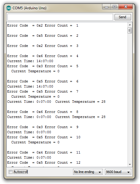
Forcing I2C Errors
If you’re like me, then you won’t be satisfied with having an error handling routine that doesn’t seem to be handling any errors. What happens if one occurs? What will it look like?
Here are a few things you can do to the code above to generate different types of errors.
- Change the timeout parameter in the I2C configuration from 250ms to 1ms.
- Change either of the I2C addresses to an incorrect value.
- Change any of the register addresses to an incorrect value.
Doing any of those three things should generate more than enough errors for you play with and investigate!
