We quickly want to examine the effects of using an AT30TS750A General Call. The temperature sensor default sampling resolution is 9bits, which we’re changing in our setup routine. By using the General Call with a Reset operations code, we can return to the default state just by issuing a quick command. However, in this module, I’ll provide the design goals for your code and the specifications for what you will need to use, and provide a set of working code you can compare against at the end of the module. This is an opportunity for you see how comfortable you are with your understanding to this point.
Objectives
- Use buttons on the Education Shield as digital inputs.
- Write a function that issues the General Call address followed by a reset command.
Background
I2C Basics
AT30TS750A Functionality Overview
Retrieving Temperature Value
Atmel AT30TS750A Datasheet
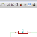
Schematic
Education Shield – AT30TS750A Temperature Sensor Subsystem
Education Shield – Shift Register Subsystem
Setup
For this module, you’ll need the following equipment:
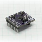
- I2C and SPI Education Shield or the AT30TS750A and Debounce Button Breakout Boards
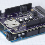
- Arduino UNO R3
1. Place jumpers on the 74HC595 Enable block along the edge of the Education Shield. This will enable the microcontroller to read button presses.
2. Mate the Education Shield with your Arduino UNO R3. If you’re using the AT30TS750A Breakout Board and the Debounce Button Breakout Board, check the labels by the pins and for the AT30TS750A connect 5V to 5V, GND to GND, SC to Analog 5, SD to Analog 4 and AL to Digital2 and for the Debounce Button Board, connect 5V to 5V, GND to GND, and B1 to Digital8 and B2 to Digitl7.
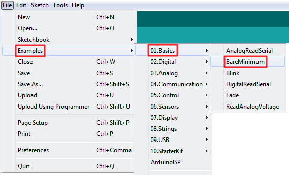
3. Finally, connect your Arduino to your USB cable, and use the Arduino IDE to upload the “Bare Minimum” sketch from the Basics section of the Examples.
Testing the AT30TS750A General Call
The General Call address is an I2C slave address, 0x00, that can be issued to allow interaction with multiple devices at the same time. We’re going to use it to reset our temperature sensor back to it’s default power up state.
The datasheet for the AT30TS750A allows for two different commands, also called Operations Codes or OpCodes to be issued after the General Call…
- 0x04 RESET ADDRESS – This is used if the three configurable address pins, A0, A1 and A2, have had their state changed and need a live reset of the I2C address of the device. This could be performed by tying those pins to GPIO pins of your microcontroller, the digital pins of your Arduino for example, however looking at the schematic for the Education Shield, you’ll see that those three pins are permanently tied to ground, so we can’t really play with this command.
- 0x06 POWER ON RESET – This command will also perform an address reset, but in addition to that, it causes the configuration values that are specified in the non-volatile configuration registers to overwrite whatever is running in the volatile configuration registers. We’ll use this to test the effects of issuing the General Call address.
Design Challenge
By this point you should be fairly proficient with the registers of the temperature sensor, how to address them with the Wire Library and reading button presses, so rather than simply give you the code (which is still provided below), I’ll give you design goals instead, on which you can base your efforts. You should absolutely reuse code from previous modules to fill in the blanks, no need to write it all from scratch.
Design Goals
- Create constants to hold the General Call address, 0x00 and the Reset OpCode, 0x06.
- Initialize the AT30TS750A using 12 bit sampling resolution when your code first starts.
- Issue the General Call address and the Reset command, when the DATA button is pressed.
- Test that the resolution has changed by sampling the temperature both before and after the reset.
Test Conditions
- Does your chip start up and provide temperature data using 12 bit resolution? This would be equal to four decimal places of data..
- Are you using the General Call correctly?
- Is the chip resetting to the default resolution stored in non-volatile RAM?

Example Code
The example code is below. Try to create the code using the design goals above yourself, before referring to it.
|
1 2 3 4 5 6 7 8 9 10 11 12 13 14 15 16 17 18 19 20 21 22 23 24 25 26 27 28 29 30 31 32 33 34 35 36 37 38 39 40 41 42 43 44 45 46 47 48 49 50 51 52 53 54 55 56 57 58 59 60 61 62 63 64 65 66 67 68 69 70 71 72 73 74 75 76 77 78 79 80 81 82 83 84 85 86 87 88 89 90 91 92 93 |
/* A sketch to use the General Call I2C address to reset the AT30TS750A on the Rheingold Heavy I2C and SPI Education Shield. Pressing the "DATA" button issues the General Call address, followed by the RESET OpCode from the AT30TS750A datasheet. Website: https://rheingoldheavy.com/at30ts750a-design-challenge-general-call-reset/ Datasheet: http://www.atmel.com/images/atmel-8855-dts-at30ts750a-datasheet.pdf */ #include "Wire.h" const int AT30TS750_I2C = 0x48; // I2C Address for the temperature sensor const int GENERALCALL_I2C = 0x00; // I2C General Call Address const byte REG_TEMP = 0x00; // Register Address: Temperature Value const byte REG_CONFIG = 0x01; // Register Address: Configuration const byte OPCODE_RESET = 0x06; // OPCode: Reset const int buttonPin = 8; // DATA button used for digital input void setup() { Wire.begin (); init_AT30TS750A (); pinMode (buttonPin, INPUT); Serial.begin (9600); } void loop() { byte tempLSByte = 0; // Holds the lower byte of temp data byte tempMSByte = 0; // Holds the upper byte of temp data float floatTemperature = 0.0000; // Holds the combined decimal value of temp data int buttonPress = 1; // Used to ensure our button press code only executes once per press // When the DATA button is pressed, issue the General Call + Reset. By setting the buttonPress to 0 // generalCallReset is only issued once per press. while (digitalRead(buttonPin) == HIGH) { if (buttonPress == 1) { buttonPress = 0; generalCallReset (); } } // Grab the temperature data Wire.beginTransmission (AT30TS750_I2C); Wire.write (REG_TEMP); Wire.endTransmission (); Wire.requestFrom (AT30TS750_I2C, 2); // Load the temperature data from the I2C buffers into our temperature variables tempMSByte = Wire.read(); tempLSByte = Wire.read() >> 4; floatTemperature = tempMSByte + (tempLSByte * 0.0625); Serial.print ("The temperature is... "); Serial.print (floatTemperature, 4); Serial.print ("C, "); Serial.print ((floatTemperature * (1.8)) + 32, 4); Serial.println ("F"); delay (100); } void init_AT30TS750A() { /* Change the resolution of the temperature measurement 0x00 = 9 bit resolution 0x20 = 10 bit resolution 0x40 = 11 bit resolution 0x60 = 12 bit resolution */ Wire.beginTransmission (AT30TS750_I2C); Wire.write (REG_CONFIG); Wire.write (0x60); // Set Measurement Resolution Here Wire.endTransmission (); } void generalCallReset() { Serial.println (); Serial.println ("Issuing Power On Reset"); Serial.println (); Wire.beginTransmission (GENERALCALL_I2C); // Select the general call address Wire.write (OPCODE_RESET); // Write the reset opcode to any device listening Wire.endTransmission (); } |

