This is an MSGEQ7 Arduino Tutorial and in it, we’re going to explore connecting the seven band graphic equalizer chip to an Arduino UNO R3 and start to get some measurable responses back. For those that have the MSGEQ7 Breakout Board, this is a great way to get started in understanding how to interface the chip with your own projects.
Setup
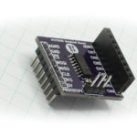
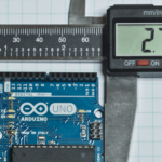
For this tutorial, you’ll need the MSGEQ7 Breakout Board, an Arduino UNO R3, some jumper wire, and some audio source connected with a normal headphone style cable, but that’s pretty much it. You’ll also want to download a copy of the datasheet for reference as well: Mixed Signal Integration MSGEQ7.
The hook up for this doesn’t really merit a schematic, since the breakout board only means you have to hookup five pins, but for the sake of completeness, the schematic looks like this…
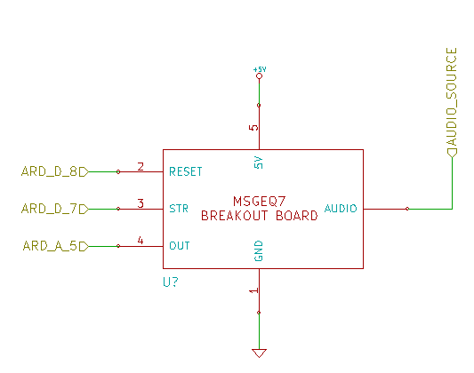
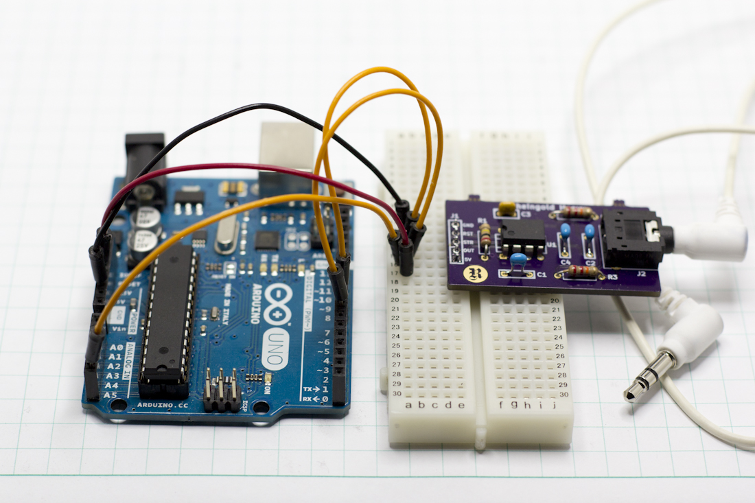
Like I said, not much to it. Here it is all hooked up.
MSGEQ7 Functionality
The graphic equalizer chip manages the process of sampling and measuring the audio frequencies you provide it automatically. The trick is getting the timing of your code down correctly to accurately reset the chip, and to manage the steps necessary to move through the frequency measurements.
The chip starts by taking the input and running it through a bandpass filter, eliminating all the frequencies except for the particular frequency band assigned to that filter, in the case of the first sample, all frequencies are eliminated except 63Hz. This remaining signal is passed through a peak detector to determine the strength in that frequency. The measurement of that signal strength is presented as a voltage on the out pin between 0V and supply voltage, which in our case is 5V (also the recommended voltage in the datasheet). In order to move from one frequency measurement to the next, you pulse the strobe pin low.
A reset sequence is required at a minimum prior to the first attempted read. Reset moves the multiplexing system, the internal guts of the MSGEQ7 that manage moving through the frequencies, to the beginning, 63Hz. From that point forward, the chip is supposed to cycle through all the readings in turn as you pulse in strobe signals, and when it gets to the last one 16kHz, it will roll back to 63Hz on the next strobe and start over.
The timing diagram published in the official datasheet looks like it was photocopied about 84 times before it wound up in the PDF, so I’ve recreated it here in hopefully cleaner form…
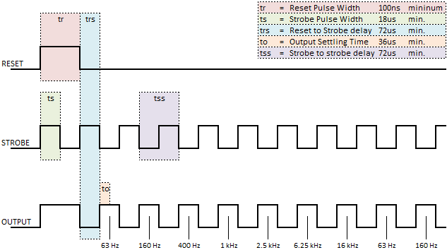
The first important thing to note from the timing diagram, is that all the values are presented as minimums. That means we don’t have to worry about getting super fine down to the microsecond with our strobe or reset, we can just use delays to keep it easy. We do have to be a little careful, because even thought digitalWrite is considered a very slow manipulation of the state of a general purpose IO pin (GPIO), it still has a pulse width of only 5us, which is well below the minimum of everything there except the Reset pulse width. The other thing to note is the sequence that must be established in order to correctly begin the reset, and what state everything needs to be in during the sequence.
I do want to make one last thing clear, in case you’re not familiar with reading timing diagrams: you have control over the reset and strobe pins, the diagram of the output signal is only indicating what’s happening on the output, not that you should raise the pin voltage high!
Programming Your Arduino
Well, let’s make this thing do something!
First our declarations…
|
1 2 3 4 |
int strobePin = 7; // Strobe Pin on the MSGEQ7 int resetPin = 8; // Reset Pin on the MSGEQ7 int outPin = A5; // Output Pin on the MSGEQ7 int level[7]; // An array to hold the values from the 7 frequency bands |
It doesn’t get much easier than that. All we do is specify that we’re connecting the strobe to digital 7, reset to digital 8 and the output to analog 5. At the bottom, we’re creating an array seven values wide that we’ll use to hold the readings from the analog pin. Now let’s get it setup…
|
1 2 3 4 5 6 7 8 9 10 11 12 13 14 15 16 17 18 19 20 21 22 |
void setup() { Serial.begin (9600); // Define our pin modes pinMode (strobePin, OUTPUT); pinMode (resetPin, OUTPUT); pinMode (outPin, INPUT); // Create an initial state for our pins digitalWrite (resetPin, LOW); digitalWrite (strobePin, LOW); delay (1); // Reset the MSGEQ7 as per the datasheet timing diagram digitalWrite (resetPin, HIGH); delay (1); digitalWrite (resetPin, LOW); digitalWrite (strobePin, HIGH); delay (1); } |
Everything is appropriately initialized, so it’s time to harvest some data.
|
1 2 3 4 5 6 7 8 9 10 11 12 13 14 15 16 17 18 19 |
void loop() { // Cycle through each frequency band by pulsing the strobe. for (int i = 0; i < 7; i++) { digitalWrite (strobePin, LOW); delayMicroseconds (100); // Delay necessary due to timing diagram level[i] = analogRead (outPin); digitalWrite (strobePin, HIGH); delayMicroseconds (1); // Delay necessary due to timing diagram } for (int i = 0; i < 7; i++) { Serial.print (level[i]); Serial.print (" "); } Serial.println (); } |
We have seven chunks of data to retrieve, so we’re going to do some FOR looping. In the first loop, we bring strobe low, then wait 100us to accommodate the output settling time. With the output settled, we read the voltage at the analog pin and write it into the array at position “i”.
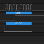
Let’s take a quick look at the output settling time specification in detail. If we look at the signal on an oscilloscope, you can see why they have that requirement…
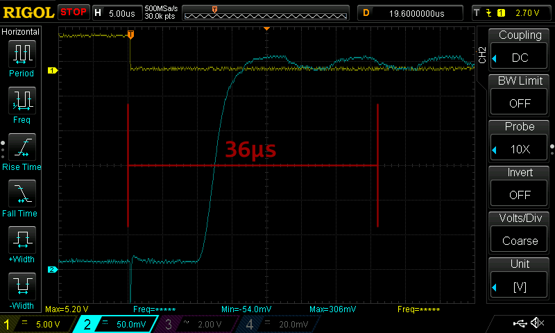
The grid is 5us per division on the x-axis, and at the top, you can see the yellow line, which represents the strobe signal. The blue line is the output value. When the strobe goes low, that tells the MSGEQ7 to output the voltage representing the frequency strength and there’s a very clear ramp the voltage takes to go from no signal to full signal. I ran this test at least a dozen times, and not once did I ever see a ramp time greater than 20us, so that 36us value includes a bit of slop in it, I imagine. Even watching the scope with a live signal that I know was jumping around from low to max back and forth, it never exceed 20us, so the datasheet is very conservative. I have no problem with that.
Once we’ve grabbed our analog value, we bring strobe high, and delay 100us again, this time to accommodate the strobe to strobe delay. Basically, the period of the signal must be at least 72us, or said differently, there must be 72us in between the falling edges of the strobe signal. I don’t think it’s stated anywhere in the datasheet, but it would seem to me that this delay is the length of time necessary for the multiplexor to move to the next bandpass filter, for the peak detector to do its thing and then get the voltage ready for being sent to the output.
The final act, is to quickly spit out our values to the serial monitor. I want to caution you, that when you get ready to ditch the serial monitor and move to making LEDs dance, you’ll want to comment out all your serial debug code. As an example, this little chunk of code that displays the seven frequency values in the serial monitor introduces a 40ms delay into our code. That’s approaching visual territory when talking about persistence of vision. However, for our purposes here, it’s fine to be able to see the values streaming up the serial monitor page.
Here is the code all in one piece…
|
1 2 3 4 5 6 7 8 9 10 11 12 13 14 15 16 17 18 19 20 21 22 23 24 25 26 27 28 29 30 31 32 33 34 35 36 37 38 39 40 41 42 43 44 45 46 47 48 49 50 51 52 53 54 55 56 57 58 59 60 61 62 63 64 65 |
/* A sketch that grabs the frequency signal level measured by the Mixed Signal Integration MSGEQ7. This sketch is designed to work with the MSGEQ7 Breakout Board available at the Rheingold Heavy website. This sketch expects the following pin assignments... STROBE = DIGITAL 7 RESET = DIGITAL 8 OUTPUT = ANALOG 5 Website: https://rheingoldheavy.com/msgeq7-arduino-tutorial-01-getting-started Datasheet: http://www.mix-sig.com/images/datasheets/MSGEQ7.pdf */ int strobePin = 7; // Strobe Pin on the MSGEQ7 int resetPin = 8; // Reset Pin on the MSGEQ7 int outPin = A5; // Output Pin on the MSGEQ7 int level[7]; // An array to hold the values from the 7 frequency bands void setup() { Serial.begin (9600); // Define our pin modes pinMode (strobePin, OUTPUT); pinMode (resetPin, OUTPUT); pinMode (outPin, INPUT); // Create an initial state for our pins digitalWrite (resetPin, LOW); digitalWrite (strobePin, LOW); delay (1); // Reset the MSGEQ7 as per the datasheet timing diagram digitalWrite (resetPin, HIGH); delay (1); digitalWrite (resetPin, LOW); digitalWrite (strobePin, HIGH); delay (1); } void loop() { // Cycle through each frequency band by pulsing the strobe. for (int i = 0; i < 7; i++) { digitalWrite (strobePin, LOW); delayMicroseconds (100); // Delay necessary due to timing diagram level[i] = analogRead (outPin); digitalWrite (strobePin, HIGH); delayMicroseconds (100); // Delay necessary due to timing diagram } for (int i = 0; i < 7; i++) { Serial.print (level[i]); Serial.print (" "); } Serial.println (); } |