In Part 9, we got in-depth with the 16Mhz crystal connected to the 16U2. Now it’s time for the big show: the Atmel ATMEGA328P. The brain of the Arduino. The right arm of the Arduino. The opposable thumb of the Arduino. When you think of the “hardware” that makes up an UNO, you don’t think of 16U2s and op-amp comparators, you think of this chip.
Build An Arduino UNO R3 from Scratch Table of Contents
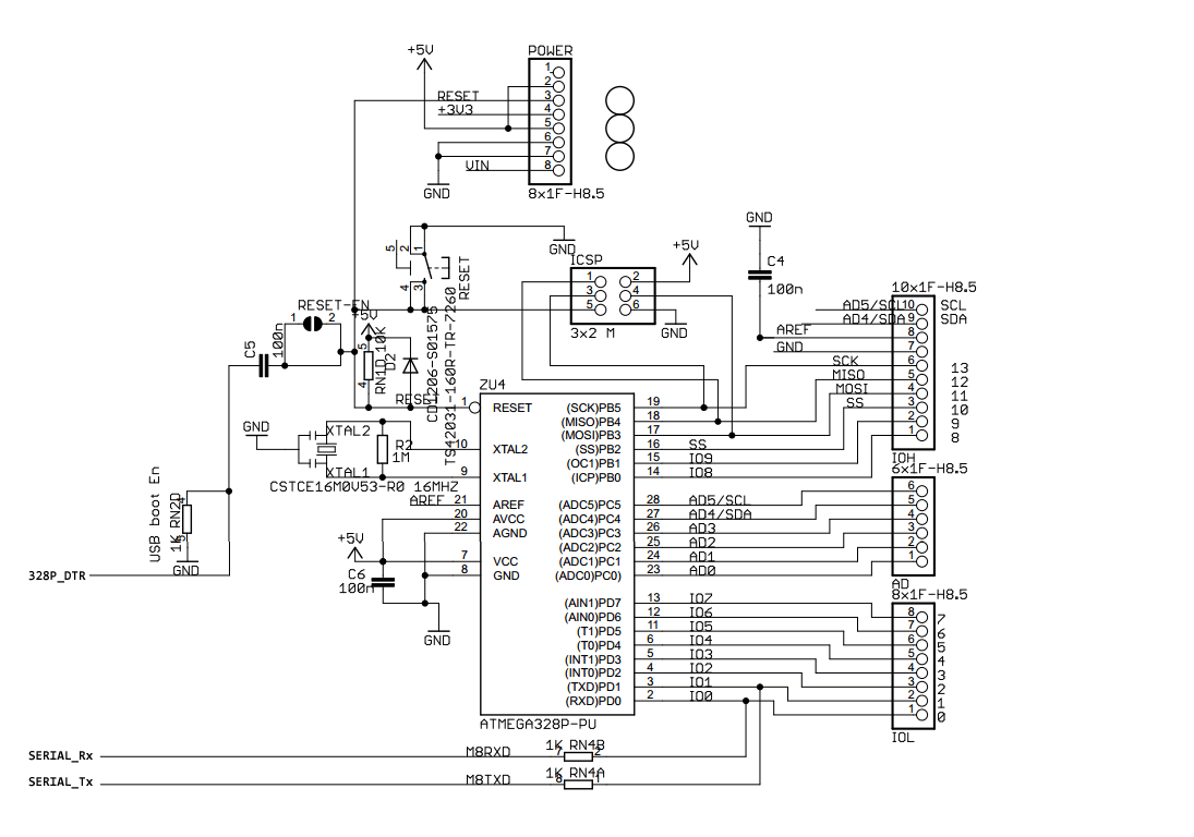
The ATMEGA328P Subsystem Official Schematic
The good news is that most of the schematic isn’t new circuitry with the majority of the pins drawn straight to the shield headers. The ICSP circuit is the same as the 16U2. The crystal circuit is the same. Bypass caps across VCC and AVCC, yep (we’ll go into AVCC in a sec). Ultimately, it’s the reset circuit that’s the newest thing on here. Remember, the schematic gets a bit big so make sure to click on it to embiggen.
In this post we’ll get into the more familiar aspects of the circuit before taking a bite of the DTR / Reset apple in the next.
Bypass and Termination
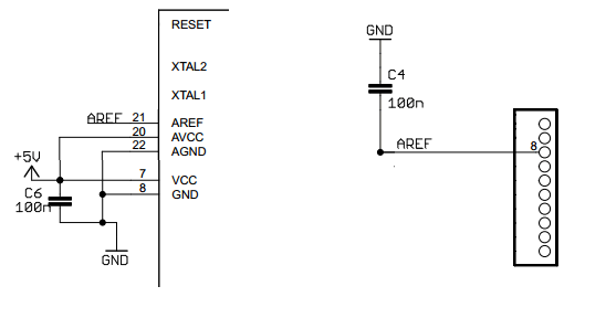
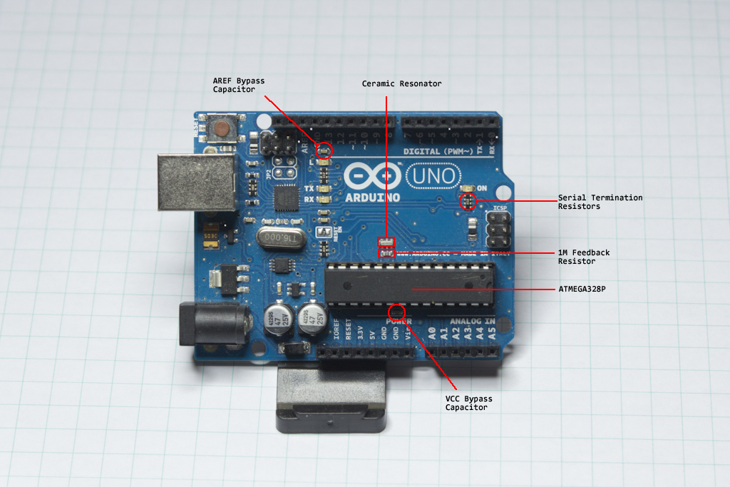
We have a set of bypass capacitors on the schematic, even if they aren’t exactly drawn in conventional ways. They are both 0.1uF (100nF) caps and connected between voltage sources and ground. The first is the main voltage source bypass cap, C6, and the second one is C4 on the AREF line. There is nothing special about these capacitors, so I’ll use the same ones I’ve been using all along.
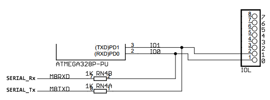
The serial lines, SERIAL_Tx and SERIAL_Rx, have 1K termination resistors on them, RN4A and RN4B. These resistors are in series between pins 8 and 9 of the 16U2 and pins 3 and 2 of the 328P respectively. The serve the same function as the USB termination resistors in the USB Subsystem. Pins 2 and 3 of the 328P are also broken out to the shield header as “DIGITAL 0” and “DIGITAL 1”, although you probably never use them that way since serial communication is about the only way to debug Arduino code. These resistors are part of one of the resistor networks on the Uno board, so I’ll put them into my schematic as individual 1K passives, but keep the whole “resistor net” in the back of my mind for later.”
16Mhz Oscillator/Resonator
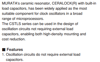
Well, here we have something a little new. Rather than use the same 16Mhz Crystal oscillator that was used with the 16U2, we have a 16Mhz ceramic resonator here instead. The internals of the chip aren’t any different, there’s still an inverting amplifier inside the guts of the 328P, and that 1M resistor is still there to provide feedback and speed up the oscillator startup time, but curiously, they’ve selected the Murata CSTCE16M0V53-R0 ceramic resonator instead. Why?
The essential difference between a crystal oscillator and a ceramic resonator, from a practical perspective, is accuracy. A crystal has it’s tolerance measured in parts-per-million (PPM), the resonator has it measured in percentages. The Fox crystal used in the 16U2 has a tolerance of 30PPM, which equates to something like 0.0031%, while the Murata resonator is +/- 0.5%. That’s a big difference! Because the timing of the USB signal is so important, I imagine that’s why there’s a crystal on the 16U2, where as the 328P can get away with the tolerance of the resonator.
Maxim Appnote 2154 does a great job summarizing the relative strength and weaknesses of various forms of oscillators, including the good ‘ol RC ticker 🙂 Microcontroller Clock—Crystal, Resonator, RC Oscillator, or Silicon Oscillator?

Another important thing to note, is that the resonator has the load capacitors already included! Which is odd, considering that they are shown on the schematic. It may be that the symbol for “ceramic resonator” in the CAD program they used showed those on there, but they have them listed as XTAL1 and XTAL2. Seriously, the data sheet essentially screams, “WE INCLUDED THE LOAD CAPACITORS ALREADY.”
So, while less accurate, we are saving nearly a dollar (in single quantities) because the load caps are already included. Even on a production run of 250 boards, we’d be saving nearly 40 cents per board by using the resonator instead of the crystal. That’s actually a very compelling savings.
Also, it’s tiny… about the size of an 0603 passive… and surface mountable.
For the 1M feedback resistor, we’ll just use the same one we had with the 16U2.
Data Terminal Ready and RESET
This part of the 328P subsystem requires a little more theory, so I’ve decided to break it into it’s own post, which will come next.