Now that we have a firm understanding of how we need to structure the signals to communicate with an I2C component, let’s look at the Arduino Wire Library that will actually manage all of that signaling for us.
Objectives
- Understand why the code is called the Wire Library and not the I2C Library
- Learn the nine Wire Library functions and their purpose
- Know which functions actually cause data to transmit and which are only preparatory
- Understand which functions are used with an Arduino Master and which are used with an Arduino Slave
Background
I2C Basics
I2C Signals
Official Arduino Wire Library Reference
Schematic
No schematic is associated with this module.
Setup
No setup is required, however you can access the files that comprise the wire library in the program folders installed with your Arduino IDE. Be very careful when opening those files though, that you don’t modify them or you’ll need to reinstall everything from scratch. Additionally, if you wish to replicate the oscilloscope traces, use any two channel oscilloscope capable of reading a 100kHz signal connected to the SDA and SCL lines between an Arduino and any I2C chip, and then send each function listed below as necessary with sufficient delay time in between to allow you to view the resulting scope trace.
The Arduino Wire Library
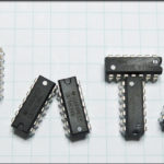
The Wire Library is a series of files in plain text that exist in the ../Arduino/libraries/Wire directory on the machine you write your code on. The library and files all contain the word “wire” because Atmel (the chip at the heart of the Arduino) devised a system called “Two Wire Interface” or “TWI” which is their flavor of I2C. There are several files in that path, including the example code that is available to you in the IDE, but the heart of I2C communications with an Arduino resides in four files…
- .\Wire.h
- .\Wire.cpp
- .\utility\twi.h
- .\utility\twi.c
Now it’s not a perfect analogy, but you can think of these files as creating a machine, where Wire.h/Wire.cpp are the parts that let you write the easy-to-understand Arduino code, and twi.h/twi.c are the parts that take your easy-to-understand code and reconfigure it to something the C compiler wants to chew on. When you’re writing Wire.begin(); , that command is defined in Wire.h / Wire.cpp. That in turn, calls twi.h/twi.c which imports a WHOLE bunch of the more hardcore libraries from various sources, such as Atmel, the chip manufacturer.
If you ever wondered exactly what makes the Arduino system so special, this is it; there is a lot of sausage being made behind the scenes that you never have to deal with.
There are nine functions created by the Wire library, that you use to make I2C magic happen with your Arduino. These are made available in your code by using the command #include “Wire.h” at the top of your sketch. I’ve listed them below in the order that you’re likely to use them.
The oscilloscope traces below were generated by setting the scope to trigger on a single negative going edge on the SDA signal bus, which would indicate the beginning of the Start Condition. Each of the functions below were executed followed with a five second delay that allowed me to capture what the scope was displaying at each stage.
Arduino Wire Library Functions – Acting as Master
Wire.begin()
This command prepares a few buffers for storing streams of data, and runs a function from twi.c called twi_init(), which is the Two Wire Interface Initialization routine. twi_init() sets a series of very specific configurations in the ATMEGA328P including the speed at which the I2C bus will communicate and prepares the interrupts necessary for it. This command has to exist in your code somewhere in order for I2C to work, and generally it’s placed in the setup portion of your code.
Wire.begin(intAddress)
Nearly exactly the same as the command above, this function joins your Arduino to the I2C bus, however it connects it as a slave component, rather than as a bus master. The intAddress variable is the 7-bit I2C address you assign to your Arduino. It can be any 7-bit address, provided it doesn’t conflict with any other on the bus.
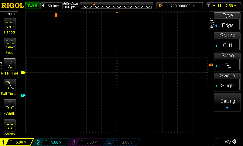
Here is an oscilloscope trace showing what appears on the SCL and SDA signal buses immediately after the Wire.begin() function was executed. As expected, nothing is happening because this is only a preparatory function.

Wire.beginTransmission(intAddress)
This is how you start talking with an I2C slave component. You imported the library in your includes, and you initialized the I2C system by using the Wire.begin() function, and now you want to actually do something. This function loads the slave address you want to talk to, intAddress, into a behind-the-scenes variable and specifies that the communication will be a WRITE action, meaning the Arduino is going to follow up the address and R/W flag with some quantity of data for the slave component.
This scope trace shows the SCL and SDA signals after the Wire.beginTransmission() function was excecuted. Again, nothing is happening because this is only a preparatory function.
Wire.write(various options)
Since you’re setting up to send data to the slave component, you use Wire.write() to load an internal buffer with the data you want the slave to receive. beginTransmission prepared the R/W flag with a W, and this is the data that you’re actually W’ing.
There are various options for the data that you transmit, but remember that all I2C communications are a single byte (8-bits) in length (not including ACK/NACK), so you have to adhere to that. The Arduino code will accept an integer value, a string to send as a bunch of bytes, or, a sequence of non-string data bytes followed by an integer indicating the amount of bytes in the sequence. You are limited to 32 bytes of data per transmission burst. If you need to write more, you’ll need to enter the stop condition and then send the next batch. This is a limitation of the buffers created in the libraries, not the I2C protocol.
The scope trace is still blank, because Wire.write() is only loading up a buffer internal to the Arduino.

Wire.endTransmission(boolStop)
With the Wire.endTransmission function, we finally cause our I2C bus to chirp something out. Specifically, the twi.c library assembles all the bits of data you provided in beginTransmission() and write(), then sends it all out. It combines the 7-bit address with the R/W flag, it sends out the data, manages listening for ACKs as necessary and creates the repeated start or stop condition. And all you had to do, was write three lines of code!
There are some interesting aspects to the endTransmission() function. First, it returns a byte value to let you know what the status of the data transmission was…
| Value Returned | Name | Description |
|---|---|---|
| 0 | SUCCESS | The attempt to write to your slave component was successful. |
| 1 | DATA EXCEEDS BUFFER LENGTH | You are attempting to send more than 32 bytes of data. |
| 2 | NACK ON ADDRESS TRANSMIT | Either the component you're attempting to talk to is offline, or you mistyped the I2C address for it. Which do you think is more likely? |
| 3 | NACK ON DATA TRANSMIT | The slave component responded to its address with an ACK, but did not respond that it received the data successfully. |
| 4 | OTHER ERROR | This means your I2C write request to the slave component failed in some other fashion, most likely dealing with gremlins. |
Second, the function accepts a boolean value that allows you to explicitly enter the Stop Condition at the end of the data you sent, or create a repeated start condition. TRUE = Stop, FALSE = Repeated Start. This isn’t entirely 100% necessary, but in some cases, specifically in a multimaster architecture, you’ll want to ensure that you maintain control of the bus by creating a repeated start, rather than releasing the bus with a stop condition.
Now the scope trace shows activity, because the Wire.endTransmission() function is what causes the Arduino to actually execute the I2C signalling sequence of establishing the Start Condition, sending the I2C address, sending the R/W Flag, etc, etc.

Wire.requestFrom(intAddress, intLength, boolStop)
So, you know how to send data to an I2C device, but how do you request it? By using requestFrom(). This function crafts the transmission of your request by structuring the address, intAddress, with a READ bit in the R/W flag position. The amount of data in bytes is specified with intLength, and that tells the Arduino how big of a buffer it should expect to fill with ones and zeros. As with endTransmission(), the boolean Stop exists to allow you to exit to a Stop Condition after transmission, or enter maintain control of the bus with a repeated start condition.
What is interesting in this scope trace, is that the Wire.requestFrom() function executes the read request, but does it using a single command, where as above, you need three commands minimum to write data to an I2C slave.

Wire.read()
After we got the data from our I2C slave component with the requestFrom() function, we now need to read the buffer out one byte at a time, and that is where the read() function comes into play. Essentially, it iterates it’s way through the buffer byte by byte allowing you to shift and move the data into appropriate variables and arrays as necessary. If you never call read(), then you’ll never get the data that was pulled with requestFrom().
The Wire.read() function only acts on internal buffers and variables, so as you would expect, the scope trace is blank.

Arduino Wire Library Functions – Acting As Slave
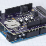
If you ever decided that you wanted to connect two Arduinos together and have them talk via I2C, you can do this by using the Wire.begin(intAddress) function above. However in order to initiate communications and supply data to the I2C bus, you have to explore a few other functions as well.
Wire.onRequest(FunctionName)
If you want the Arduino, that is acting as the slave component, to perform a specific action when the master component wants to read data from the slave, you define that using onRequest(). You would have some code that performs an activity, like checking the voltage level of an analog pin, in a function, and then that function would be called to generate and prepare the data when the slave component receives the request in the form of an incoming address+R from the master.
Wire.onReceive(FunctionName)
Alternatively, if you want the Arduino acting as the slave component to perform a specific action when the master component wants to write data to it, you define that using onReceive(). Again, you would have some code that performs an activity, like taking the received data and using it to set a PWM level, and then that function would be called to execute against the data received after the request is sent in the form of an incoming address+W from the master.
Wire.available()
This final function of the Wire library returns the amount of bytes that have been transmitted to an Arduino acting as a slave component. If 5 bytes were transmitted, Wire.available() would return the value 5. That would provide you with the value required to start an iteration loop to cycle through the individual bytes that had been transmitted.
All three of the slave oriented functions only act on internal code, so no signal traces occur during their execution. All signalling is initiated by the master, so it follows that the scope would be blank during these functions.