The whole point of the optoisolator is to help electrically isolate one part of your circuit from another. I wanted to see if I could use my cardboard tube / LDR / LED construction to do that.
Let’s take an example circuit: we have something that is very temperature sensitive and if it rises above a certain threshold temperature, we turn on a fan to cool it off – the temperature will dictate if the motor turns on.
Here is the first circuit one might come up with to solve the problem.
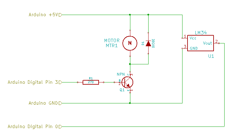
You’ll need the following components to put the whole thing together…
- Texas Instruments LM34 Temperature Sensor
- 130 Size Hobby DC Motor
- N4001 Diode
- 2N3904 NPN Transistor
- 270Ω Resistor
DIY Optoisolator Circuit #1
Using a minimum of components, you have an LM34 temperature sensor, a motor with a flyback diode, and a simple NPN transistor with a current limiting resistor. We’ll write a sketch that measures the temperature from the LM34 on Analog 0, and if it exceeds some value, turns on the PWM output on Digital 3 to turn the fan on, and cool off the temperature sensor.
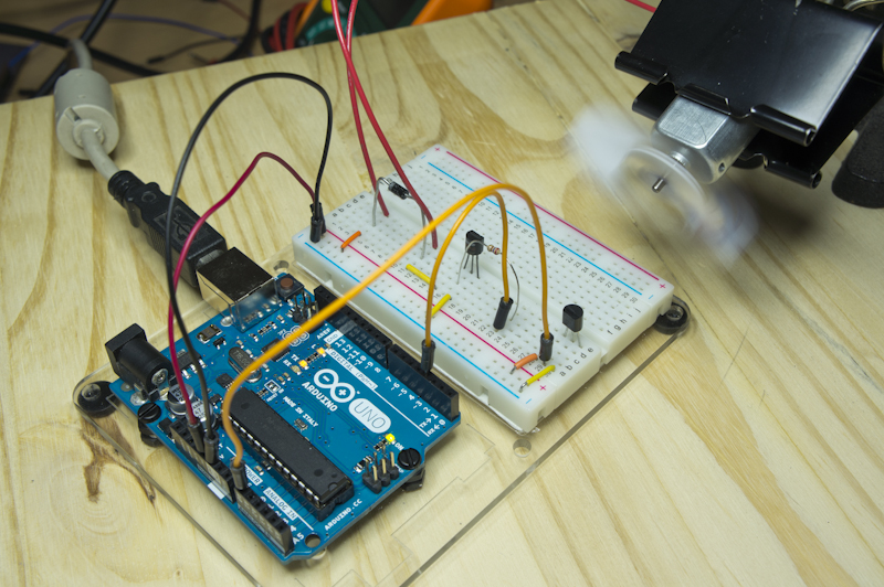
Since we’re powering the motor right off of the Arduino, we need to be careful, because the motor can draw a lot of current. Each of the digital pins are limited to 40mA, the 5V pin is limited to 200mA and the board as a whole shouldn’t be putting out more than 200mA. So, if we plugged the motor directly into one of the digital pins and just said digitalWrite (motorPin, HIGH); we’d burn that pin out almost instantly. Instead, we are going to power the motor off of the 5V pin, and sink the current through the NPN transistor. When there is 0V at the Base, no current will flow Collector – Emmitter. When I turn PWM on, it will start the current flowing once we exceed the breakdown voltage at the Base.
(I had to choose whether I was going to write up this whole optoisolator thing, or some notes on NPN transistors first – this won out because it seemed like a cool idea. I’ll put up the transistor notes next so that the paragraph above makes more sense if it left you totally cold.)
|
1 2 3 4 5 6 7 8 9 10 11 12 13 14 15 16 17 18 19 20 21 22 23 24 25 26 27 28 29 30 31 32 33 34 35 36 37 38 |
/* Controlling a cooling fan using analog temperature input. This code uses the smoothing algorithm from arduino.cc. https://rheingoldheavy.com/noise-control-with-diy-optoisolator */ // Setup the pins we're going to use int motorPin = 3; int tempPin = 0; // Setup our global variables int motorSpeed = 0; const int numReadings = 25; int readings[numReadings]; // the readings from the analog input int index = 0; // the index of the current reading int total = 0; // the running total int averageTemp = 0; // the average void setup() { pinMode (motorPin, OUTPUT); pinMode (tempPin, INPUT); // Clean out and prep the readings array for (int thisReading = 0; thisReading < numReadings; thisReading++) readings[thisReading] = 0; Serial.begin (9600); } void loop() { total = total - readings[index]; // Remove the previous reading from the running total readings[index] = analogRead(tempPin); // Read from Analog 0 total = total + readings[index]; // Add the latest reading to the running total index = index + 1; // Advance to the next position in the array if (index >= numReadings) index = 0; // If we reach the end of the array, set the index to 0 averageTemp = total / numReadings; // Calculate the average values. if (averageTemp > 163) motorSpeed = HIGH; // If the temp rises above 79.6F, turn the fan on. else motorSpeed = LOW; // Otherwise, keep the fan off digitalWrite (motorPin, motorSpeed); // Set the motor to it's output state Serial.print (averageTemp); Serial.print (" : "); Serial.println (motorSpeed); } |
The datasheet for the LM34 says that .10Vout = 1°F and I’ve decided I want the fan to turn on if it gets above 80°F. If the ADC reads a voltage greater than .80 volts, spank the fan. Each step of the 10-bit ADC = 5.00V / 1024, so…
\[\large \mathtt{\frac{.80V}{\left (\frac{5.00V}{1024}\right )}=163.8}\]I’ll round that down to 163, because I want to be on the low side of 80 when the fan turns on. After loading the sketch into the Arduino, everything looks fine, the workbench in my lab under the fluorescent light is about 77°F, so not much going on, fan-wise. All I have to do is pinch the LM34 between my fingers though and the temp starts to go up.
First I’m going to do it with the fan disconnected, so I can see what the curve is with just ambient air to cool it off.
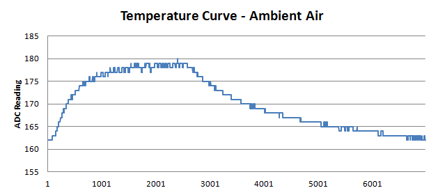
Certainly takes a while, but it’s a very smooth gradient. The little wiggles up or down are the little changes that the smoothing algorithm can’t iron out, but really, this isn’t too bad at all, and on the cooling side of the curve you only see individual steps downward each time.
Now let’s do this again with the fan connected.
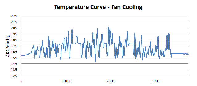
Now that’s a mess! To be fair, it does look like it cooled the thing back down in half the time, but you should have heard that fan: stop/start/stop/start/stop/sta.a.a.a.a.a.rt/stop…start/stop. Why is this happening?
Noise!
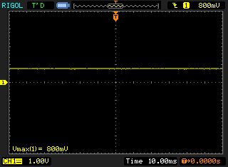
1. Clean Signal
When you look at it with the oscilloscope, you get a very nice clean signal while the circuit just sits there merrily measuring temperature without a care in the world. Then, when you turn on the fan, *wham*, it all goes to hell.
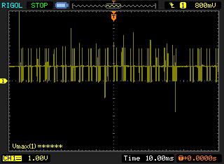
2. Electrical Noise
Every time that fan spins, the coil charges up and it creates absolute signal havoc. When the fan stops, the coil discharges, there are voltage spikes everywhere, and all of that is feeding into the circuit in myriad ways. The problem is that when one of those spikes or troughs affects the ADC, it’s feeding back into the logic that tells the fan to stay on or turn off. Looking at that graph, any time you see something above 195, that was interpreted as a temperature above 95°F, and the spikes in the middle above 205 were as sweltering 100°F. I’ve been sitting in the lab this whole time and I can promise it never got that hot.
The solution to this, is to try to isolate the noisy part of the circuit from the sensitive part.
DIY Optoisolator Circuit #2
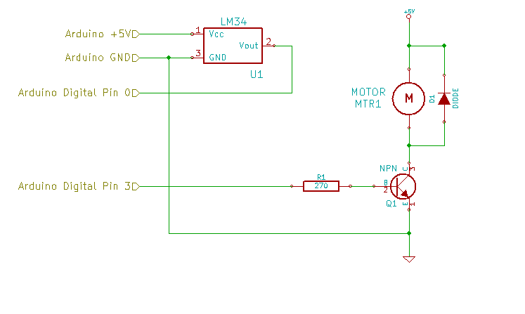
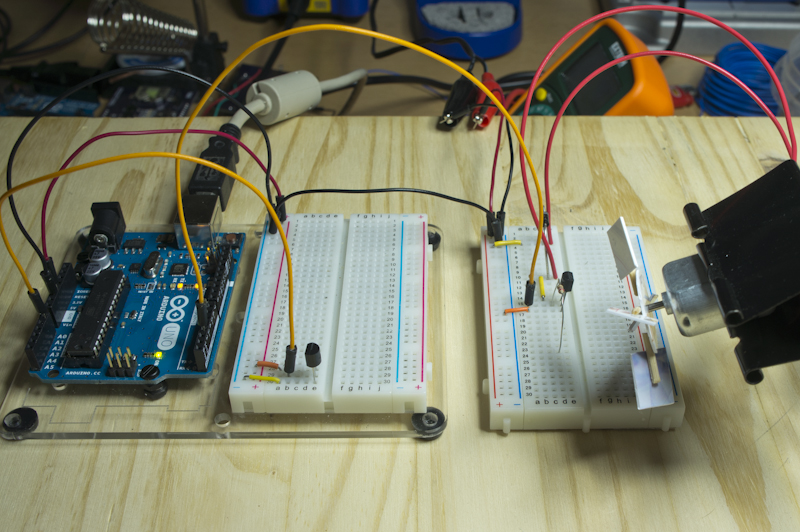
So, firstly, we’re going to move all the motor stuff off of this breadboard, and onto it’s own. But that really isn’t going to make that big of a difference, since you’d still have jumper wires connecting everything.
We really need to provide it with some voltage source, other than the Arduino, and see if that will solve the problem.
I’m going to use a 5V source I have already, but a 9V battery with a 5V regulator on it would work just as well, whatever you have on hand to get that thing as isolated as possible from the ADC. In the end, the only connection between the motor circuit and the Arduino is the PWM signal to turn the fan on, and a common ground reference between the two halves. The motor is connected to 5V as before, the NPN transistor is still acting as a current sink, and Arduino PWM from pin 3 is still being used to turn the transistor Base on and off, but with the voltage source moved to a different supply, we hope to see a cleaner signal back into the ADC.
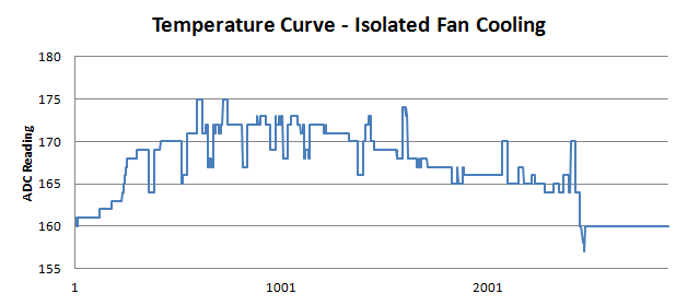
Looks more like a curve, but there’s still a lot of lumpiness. Ideally, we should be seeing the same sort of curve as the ambient cooling, but faster. Instead we still see hiccups all over the place and that weird little burp at the end.
This is where the optoisolator comes in. We need to fully decouple the noisy motor circuit electrically from the sensitive ADC circuit.
Optoisolator Circuit #3
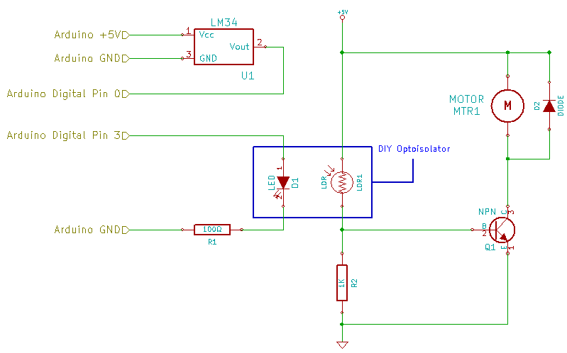
We’ve already given the motor and independent source of power, but we had to leave a common ground reference so that the PWM signal would work. If we change that PWM signal into something optical, instead of electrical, we’ll solve the problem! So, now we are going to add the optoisolator circuit in from the DIY Optoisolator post, and use that to clean up all the noise.
We do have to add more parts, obviously. We’ve got the white LED and the corresponding 100Ω current limiting resistor to form the light generating portion of our opto. On the other side, we’ve got the Light Dependent Resistor (LDR) and it’s corresponding 1K resistor forming a voltage divider. The base of the Q1 now receives a signal from the middle of the voltage divider, instead of from the Arduino PWM pin, and when the signal exceeds the breakdown voltage required, the fan will turn on. The Q1 base is being fed directly from the +5V rail with the LDR sitting in the way as voltage controller. The PWM signal now enables the LED inside the cardboard tube.
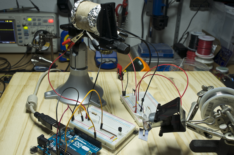
LED Shines = Resistance of the LDR Drops = Motor Turns On.
But since there isn’t a single electron flowing either to or from the Arduino to that noisy-ass motor, we should see a totally smooth curve!
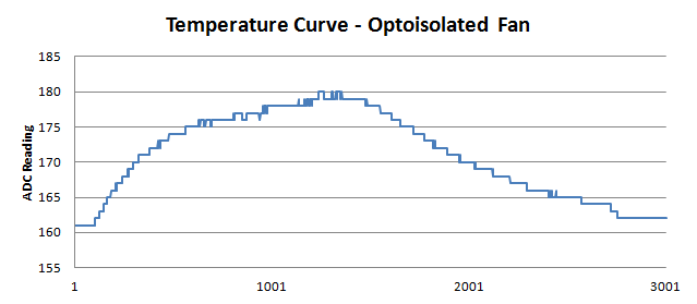
And look at that! The temperature ramp up at the start you can just ignore, that’s just my fingers pinching the sensor to transfer body heat into it, but the curve at the right is almost linear back down to the low 160s. Compare that to the exponential rate at which the ambient curve cooled off. That’s the effect of the fan blowing cooling air across the body of the temperature sensor. You can also see how clean the curve is too, no spikes at all.
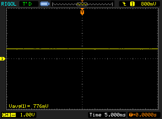
Voltage Signal at Low Temp
When I pulled that up on the oscilloscope, it was really hard for me to find a way to show that anything had changed at all, that’s how clean the signal from the LM34 is when the motor gets isolated optically.
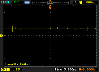
Voltage Signal at High Temp
If you look in the lower left hand corner of the two screen shots, one shows an average voltage of 776mV, 77.6°F and the other shows 860mv, 86.0°F. You can really hear the difference too – when the motor turns on, the motor stays on; and when the motor turns off, the motor stays off. No hiccups and no burps in that signal at all. In fact, it worked so well, it was hard for me to get the sensor temperature as high as I did for the ambient reading… took me three tries, and I had to turn the fan to the side!
I rewrote the loop() code to see if PWM would actually work. Now, instead of just turning the fan on and off, the fan will run at 1/2 speed from 80°F to 85°F and full speed above that.
|
1 2 3 4 5 6 7 8 9 10 11 12 13 14 15 16 17 18 |
void loop() { total = total - readings[index]; // Remove the previous reading from the running total readings[index] = analogRead(tempPin); // Read from Analog 0 total = total + readings[index]; // Add the latest reading to the running total index = index + 1; // Advance to the next position in the array if (index >= numReadings) index = 0; // If we reach the end of the array, set the index to 0 averageTemp = total / numReadings; // Calculate the average values. if (averageTemp < 163) motorSpeed = 0; if (averageTemp > 163 && averageTemp < 175) motorSpeed = 128; // If the temp rises above 79.6F, turn the fan on half. if (averageTemp >= 174) motorSpeed = 255; // If the temp rises above 84.9F, turn the fan on full. analogWrite (motorPin, motorSpeed); // Set the motor to it's output state Serial.print (averageTemp); Serial.print (":"); Serial.println (motorSpeed); } |
Now it’s a little hard to tell what half and full speed are, since I can’t measure wind velocity or RPM or anything like that. But I can measure the current draw of the motor, and at PWM level 128 into the opto, the motor draws 100mA. At PWM level 255, it draws 110mA. I don’t have a datasheet for the motor; the best I could find was a “technical details” page at Adafruit, and that states that under no load, you would draw 70mA with an RPM of 9100. So we’re at 30 / 40 mA higher than the current it draws with no load on the shaft. The farkled together fan made of old laundromat payment card and toothpick seems to make it torque up a teeny bit. Without specs or a chart of some sort from the manufacturer though, I can’t really tell what’s going on.
Bottom line, the motor draws different amounts of current depending on how fast I pulse the LED, and that’s pretty cool!
