March 28, 2015
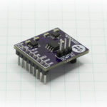
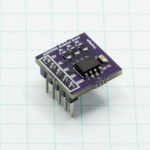
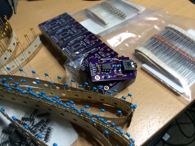
The production boards arrived last Thursday, the same day I got back from a month giving I2C workshops in Europe, and today the last box of production through hole capacitors arrived. I did an immediate dryfit to make sure the Stereo Jack now mates flush with the edge of the board and it’s absolutely perfect. All the parts are here, and I already soldered one together to test that everything and everything functioned! 100% success! I’m going to spend the weekend putting the individual kits together and will reserve the required amount to fulfill the requests of the former backers of the abandoned kickstarter that start all of this to begin with.
The product page is here: Rheingold Heavy MSGEQ7 Breakout Board.
January 29, 2015
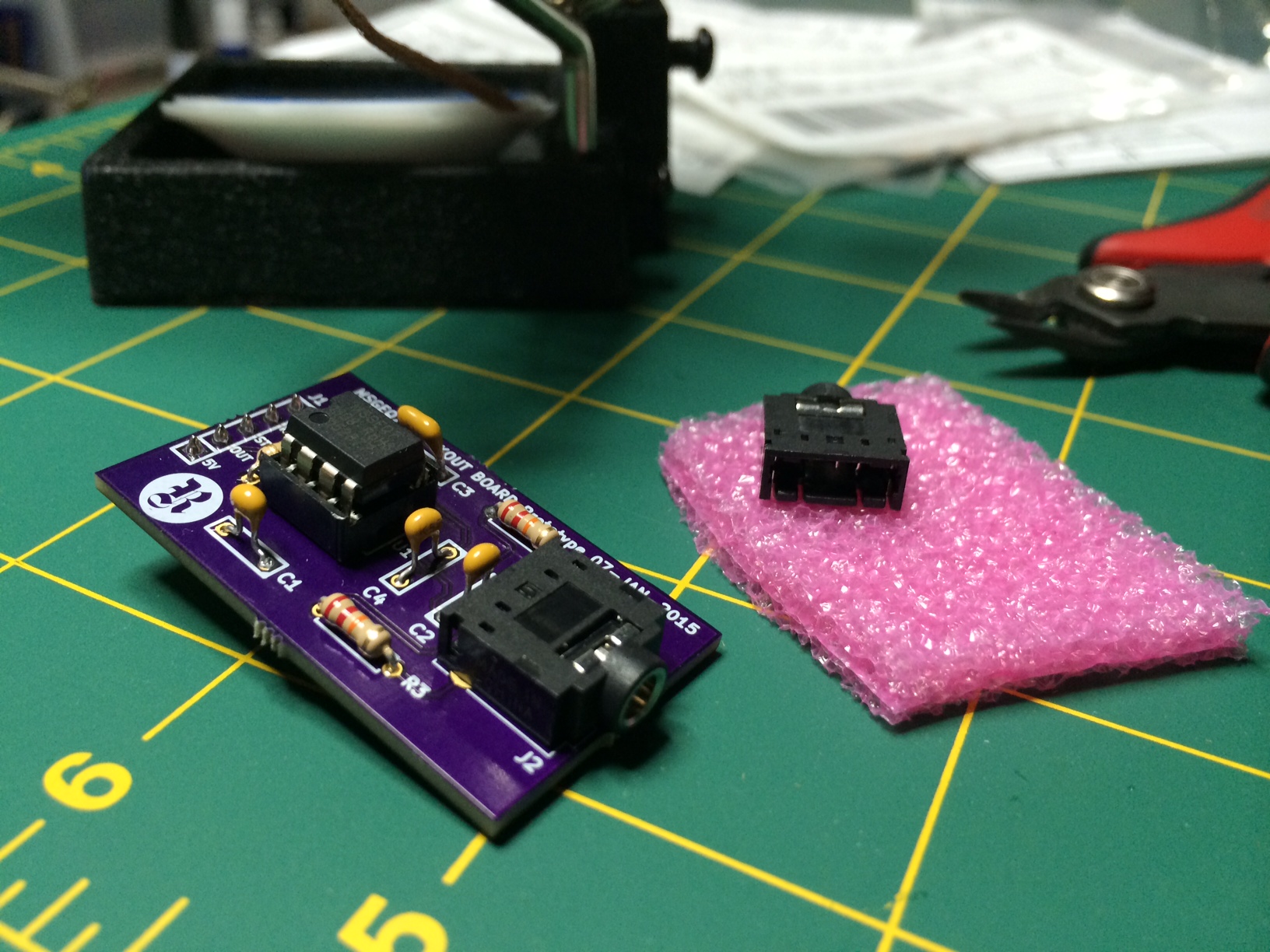
The official BOM parts arrived today and everything checks out, except for the bypass capacitors, which I accidentally ordered as 0.01uF instead of 0.1uF. I’ve modified the BOM accordingly. Pesky zeros. That’s about as harmless a mistake as I can make though, so no biggie. The important thing was checking out the footprint of the 3.5mm stereo jack, and the pins all line up, but it needs to be moved closer to the edge of the board.
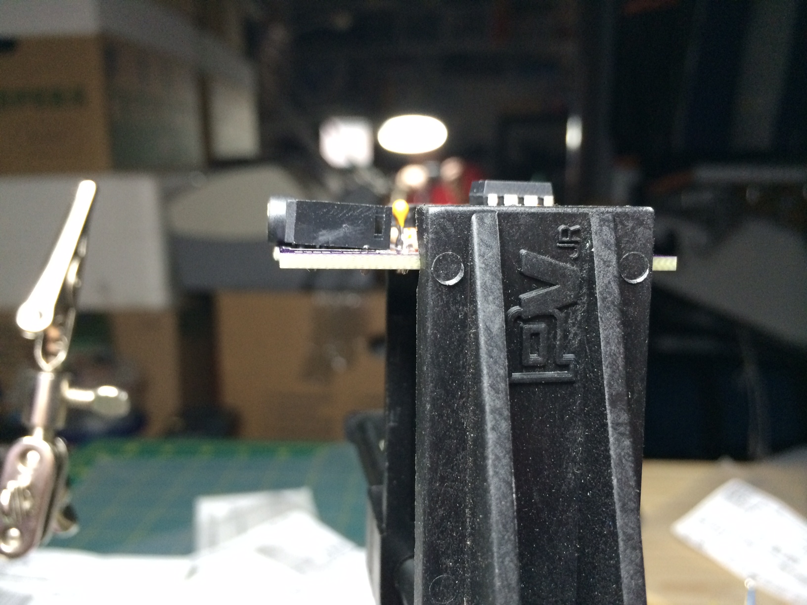
The component has a surround at the entry point of the jack, that extends below the plastic body. Since the pins are set back from the edge, it’s not allowed to hang over as, apparently, it wants to. That’s ok, as all I need to do then is move the pins forward slightly and maybe curve in the edge of the board right there. I also need to take into account that it DOES hang over the edge and not put mousebites right at that point since they would obviously impact.
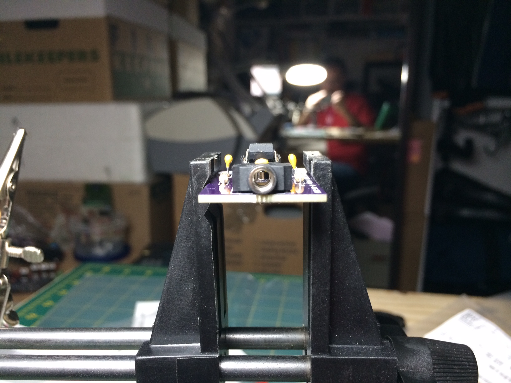
That said, the inherent functionality of the board is spot on. The test code I put together works beautifully, the board works beautifully and the chip works beautifully. I’m gonna call this prototype a success and go forward with the following official revisions for the final production design.
- Change drill size for the header from .038 to .040 (SIL vs. CONN_HEADER footprint)
- Change pin spacing for 33pF capacitor from 5mm to 2.5mm.
- Increase space between drills for the resistors from .300 to .350 to make it a little more forgiving.
- Move stereo jack footprint towards edge to accommodate component face overhang.
- Replace prototype silkscreen language and logo with production versions.
January 22, 2015
The prototype boards arrived the day before yesterday, and I had a chance to play around with the component for a bit before hand, and started to get very frustrated. I’ll write an entire education post on how to work with the MSGEQ7, but basically, you have it stream out a voltage between 0V – 5V (technically 0V – VCC) which you sample with an ADC, like the Analog pins on an Arduino. Well, after writing some quick code, then tweaking, then tweaking some more, then realizing I had forgotten to connect the reset pin, I had it streaming back values. I have a little app on my iPhone that generates tones at whatever frequency you want, so I loaded it up with the values that are the peak frequencies that the MSGEQ7 measures, the idea being that the ADC should go ballistic when that part of the spectrum is measured. It worked perfectly, EXCEPT, I could never get it to measure the spectrum from the same starting point. Ever time I reset, 63Hz would show up randomly as the fifth frequency sampled, or the 3rd frequency… totally random. I rewrote the reset code about 20 times, trying to match the timing diagram in the datasheet as closely as possible.
Turns out my breadboard is worn out and the reset pin wasn’t actually making solid contact.
I finally had time last night to solder up one of the prototype boards and boom! It worked right out of the box! I still don’t have the official parts yet, so I made it with passives out of my parts bin and a funky stereo jack I found in a junk bin at AllElectronics, but it absolutely works.

Things that need to be fixed…
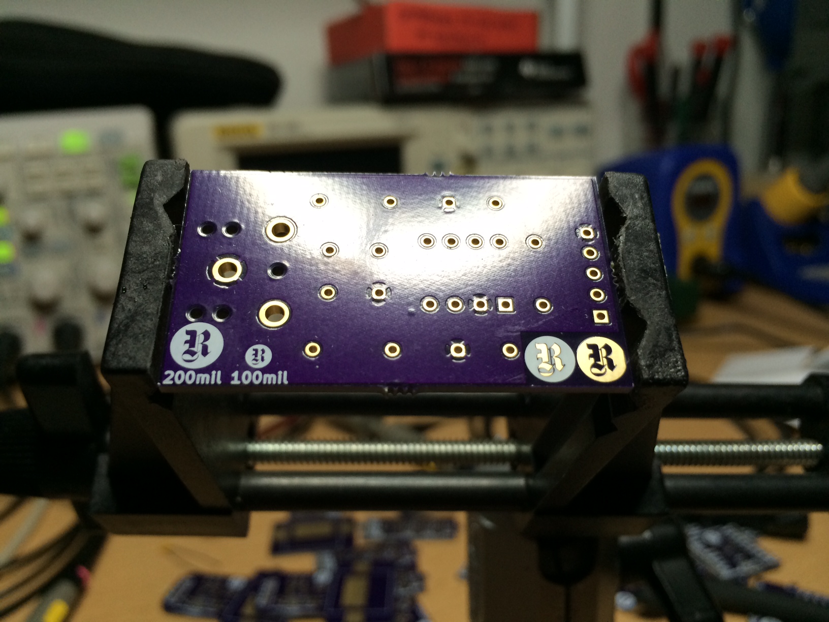
- The drill sizes for the pin header are WAY to small. I had to tap the header in with a finishing hammer. They need to be enlarged
- The drill sizes for the passives seem to fit perfectly, but I had solder leak through to the top side, so they might need to be tightened up. I’ll need to re-check this with the production parts when they arrive.
- Spacing between the resistor pins works, but could be a little wider just so you don’t have to bend the resistor leads RIGHT at the body of the component.
- Clean up the logos. All the logo tests I had on the board worked surprisingly well, even the exposed copper “R” inside the silkscreen. Pick one and use it.
January 13, 2015
Just received word that the chip order from Mixed Signal Integration is waiting for me at the Fed Ex store down the street. I’ve had two Digi-Key orders stolen from my doorway so I’ve taken to adding “hold at location” requirements to all orders that won’t fit in the mailbox. This is kind of a pain in the ass, but I do like having the extra security. Particularly for this shipment.
Of course, the fun part is that I get to walk down Sunset Blvd on a beautiful winter day in Los Angeles, which means wandering down past El Compadre and The Pikey.
The prototype boards have been panelized and assigned to the fab by OSH Park, so I expect those are still about two weeks out.
Still waiting on Digi-Key to authorize my business account so I can get the passives ordered.
January 7, 2015
Reviewed previous notes on drill issues and found the solution to combining the drill files. There is an EXPORT AND MERGE feature in GERBV. I’ll write up a post about it: Combining KiCad Drill Files
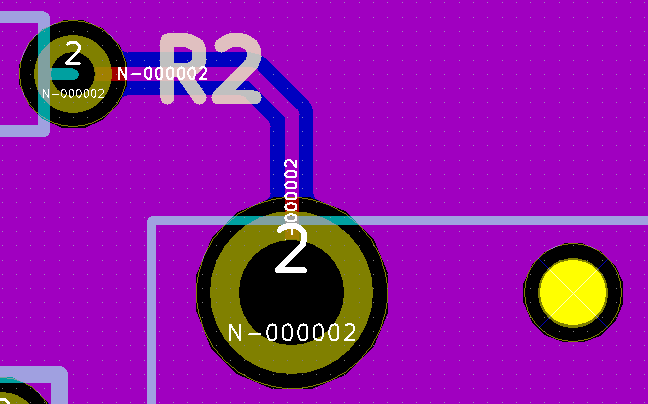
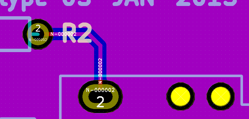
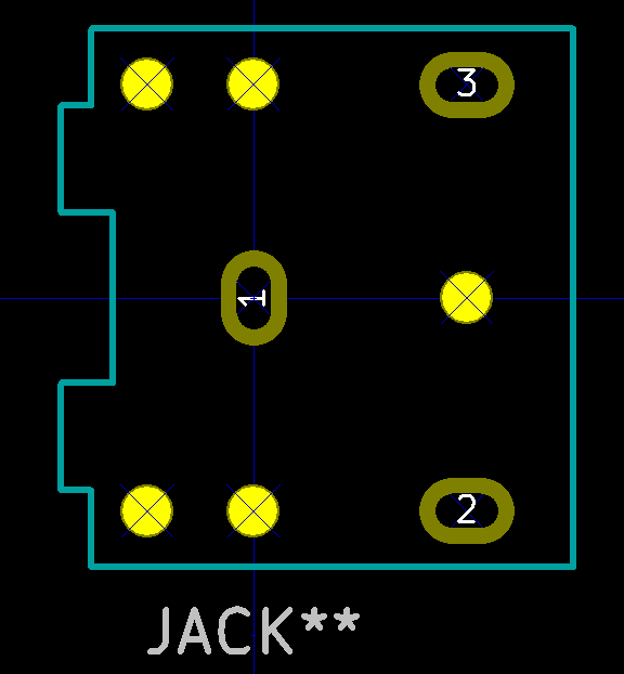
I also checked on the oval plated through holes for the stereo jack and it looks as though I hadn’t actually accomplished that before… in fact, plated ovals are very uncommon, apparently… at least in the fabrication circles I’m able to swim in right now. So I made the PTH drills ridiculously large. The problem is that the datasheet shows the preferred layout with rectangular slots of 1.50mm x 0.80mm used for a pin size of 1.00mm x 0.20mm. So, if a = 1.00mm and b=0.20mm then Pythagorean’s Theorem says the distance from corner to corner of that pin is 1.40mm. Since they add half a millimeter in their drawing for each dimension, I did so as well, resulting in round drills for the rectangular pins of 1.9mm drill size with a 1mm annular ring surrounding it. That should make for a nice meaty bit of copper for people to solder to. You can compare this with the graphic above…
I ran it through the preliminary Gerber upload process at OSH Park and it passed through without an issue. All I need is some business / non-technical clarifications from OSH Park and I can get this in the fabrication process.
(The GitHub Commit below contains fully functional gerbers that are compatible with OSH Park, however the drill sizes for the stereo jack are 1mm larger than necessary, since I originally calculated for the layout size rather than the actual pin size. Just means more solder. The official prototype gerbers that OSH Park winds up using will get their own commit.)
Click here for the files associated with this update at the Rheingold Heavy GitHub repo.
January 6, 2015
Generated the gerbers and verified them in GERBV. Everything looks good, and I added some logo tests to the board since it has the room on it. I’m checking to see how various combinations and sizes of things look: silk screen only, copper circle with “R” in soldermask, and a copper “R” with the circle in silk screen. I’ll be interested to see how they look when they come back.
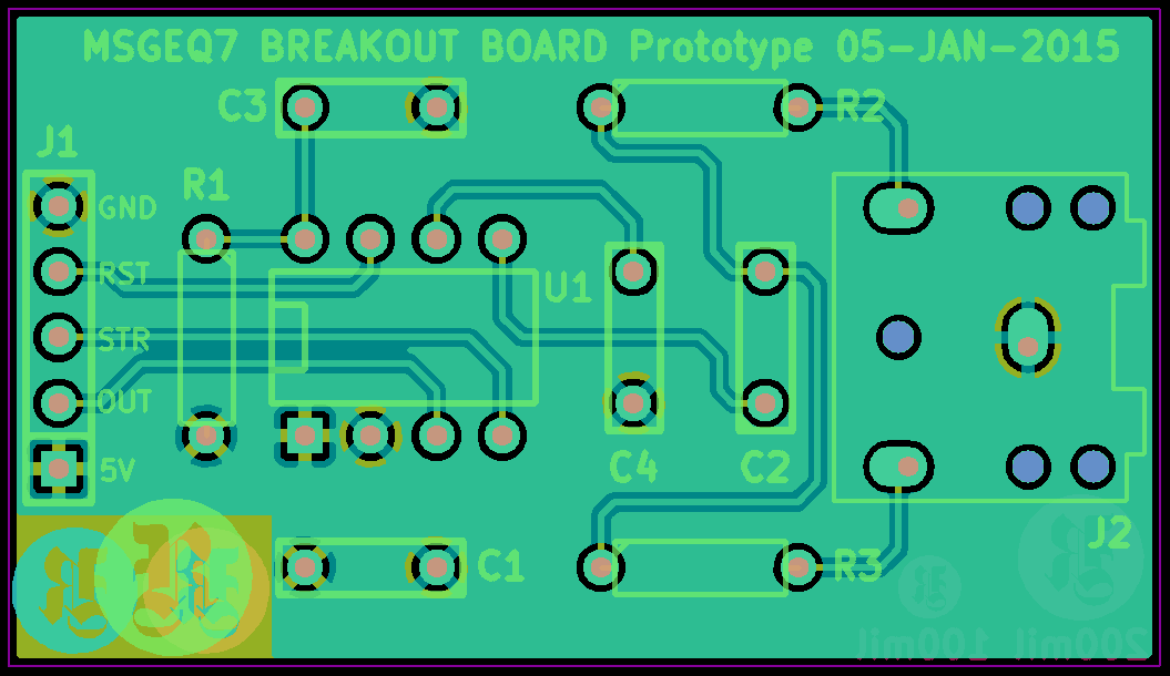
Unfortunately, I can’t just submit them to OSH Park as I’d hoped. KiCad generates two drill files when it detects mechanical holes, in this case, the non-plated holes for the 3.5mm stereo jack. OSH Park can only handle one drill file and I have no idea how to combine the two in the correct way so they know how to handle it. I’ll be in contact with their very helpful support staff tomorrow about it. Additionally, the actual electrical contacts on the stereo jack are spade shaped, not pins, so simple round holes won’t work, unless you crush them down with pliers, which I don’t want to do, even for the prototype. I need to figure out how to submit those sorts of drills to OSH Park. I’d swear I’ve done it on a previous board somehow. Anyway, another question for OSH Park support. The support staff is going to be sick of me tomorrow, as I’m about to have nearly 150 boards on order with them.
Click here for the files associated with this update at the Rheingold Heavy GitHub repo.
January 5, 2015
The response to my post about Recovering an Abandoned Kickstarter was very positive and has generated sufficient interest that I have started the prototyping process for the breakout boards.
Just before Christmas I received word from Mixed Signal Integration that the schematic I had submitted to them was valid. There were a few interesting points on it that seemed odd, such as the CLKIN pin only having a filter on it comprised of a 200K resistor and a 33pF capacitor. However, it all checked out. I received clarification from MSI:
“The RC on pin 8 (CLKIN) is not a filter, it is an RC network to create an oscillator. Inside the MSGEQ7 is a comparator with a switch tied to the output. Pin 8 will rise from 1/3 VDD to 2/3 VDD before being reset back to 1/3 VDD. This is how we do a 1 pin oscillator and not require 2 pins like many other devices need.”
This, of course, makes far more sense 🙂
I went through Octopart and selected very affordable through-hole components to use for the prototype BOM. All of the parts had direct matches in the KiCad footprint library, with the exception of the 3.5mm Stereo Jack, which I had to build myself.
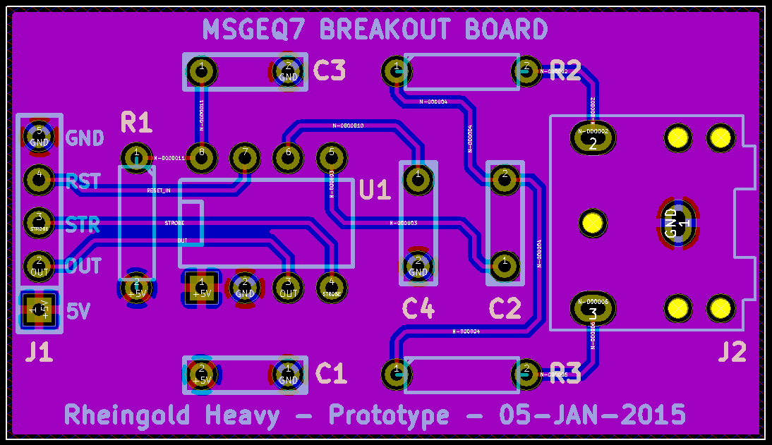
Layout for the prototype was pretty simple, refreshing actually. I kept in mind that the design was intended to be produced as a kit, since that was the primary desire of those that contacted me, so all components have their solder points at least 0.15″ from any other location, which should make it very easy to assemble, at the expense of having a slightly (ok much) bigger board than if I’d gone with my usual array of SMD parts. All copper traces are run on the top side copper, which includes a 5V power plane. Bottom side copper is a GND plane. That gave loads of room to run nice fat .010″ traces.
I’ve added the typical prototype silk screen messages to it as well, and will submit it for fabrication as soon as the new business finances are squared away. Hopefully tomorrow.
Click here for the files associated with this update at the Rheingold Heavy GitHub repo.
