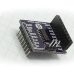
This tutorial will explore how to build a temperature display using the AT30TS750 on the I2C and SPI Education Shield and the I2C Display v2.
Background
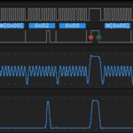
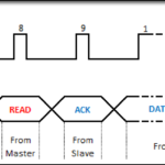
I2C Basics
Changing the I2C Library
IS31FL3728 Datasheet
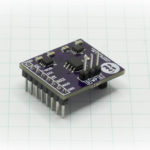
AT30TS750 Datasheet
AT30TS750 Functionality Overview
AT30TS750 Retrieving Temperature Value
AT30TS750 Temperature and Display
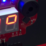
Being able to make something practical is just as fun as blinking LEDs, playing with color mixing and making larson scanners. The I2C and SPI Education Shield has several data gathering chips on it, one of which is the AT30TS750 temperature sensor from Atmel. It’s not a complicated chip to work with, and I’ve linked to several tutorials above if you need to get some of the basics for how to work with the chip. Our goal will be to query the chip for the current temperature (to the nearest 0.5° C) and display that value on the I2C Display, complete with a decimal place and degree symbol.
The plan for how the code will need to run is pretty straight forward:
- Set up our register constants
- Initialize whatever needs to be initialized
- Query the temperature sensor for the current value
- Prep that value to something that can be displayed
- Update the display
The register lists have been documented across all the previous tutorials, so I’ll just paste those values in from their original code to save time. While thinking ahead to what we’re going to do, we’ll need to display numbers in the digit display so we’ll need to copy in the code for the number pattern array as well. Since both chips are I2C based, all we need is the I2C library to interface with them, and for this implementation, we’ll keep their initialization simple. Retrieving the temperature data is a simple I2C Read operation, but prepping the value for display may take a bit of work just because there are values to the left of the decimal place, values to the right of the decimal place, and the decimal place itself, plus a degree symbol we need to conjure up. The final act of writing the value to the display is pretty simple too, since we’ll have numbers to work with, that should correspond easily to the number pattern array.
Declarations
If you’ve gone through the AT30TS750 and I2C Display tutorials, then nothing in the declarations area should look new to you: it’s all registers and constants that we’ve worked with in the past. The degree symbol pattern was created using the I2C_Display_v2_Pattern_Generator, and added here as a constant for use in our sketch.
|
1 2 3 4 5 6 7 8 9 10 11 12 13 14 15 16 17 18 19 20 21 22 23 24 25 26 27 |
#include "I2C.h" // Include the I2C library // AT30TS750A Temperature Sensor Constants const byte AT30TS750_I2C = 0x48; // I2C Address const byte AT30TS750_R_TEMP = 0x00; // Register Address: Temperature Value const byte AT30TS750_R_CONFIG = 0x01; // Register Address: Temperature sensor configuration // IS31FL3728 LED Driver Constants const byte IS31FL3728_I2C = 0x60; // I2C Address. Driver Address Pin is Tied Low. const byte TOP_R = 0x01; // top red LED in RGB die const byte TOP_G = 0x02; // top grn LED in RGB die const byte TOP_B = 0x03; // top blu LED in RGB die const byte DIG_D = 0x04; // extra marking LEDs in display const byte DIG_3 = 0x05; // Number 3 display in 0 1 2 3 order const byte DIG_2 = 0x06; // Number 2 display in 0 1 2 3 order const byte DIG_1 = 0x07; // Number 1 display in 0 1 2 3 order const byte DIG_0 = 0x08; // Number 0 display in 0 1 2 3 order const byte IS31_R_CONFIG = 0x00; // IS31FL3728 Configuration Register const byte IS31_R_BRIGHT = 0x0D; // IS31FL3728 Brightness / Audio Gain Register const byte IS31_R_UPDATE = 0x0C; // OpCode used to latch display update const byte DUMMY_DATA = 0xCC; // OpCode needs to be sent dummy value const byte DEGREE_SYM = 0xC6; // Degree Symbol Bit Pattern const byte numPatterns[20] = {0x7E, 0x0C, 0xB6, 0x9E, 0xCC, 0xDA, 0xFA, 0x0E, 0xFE, 0xDE}; // Speaker and IS31FL3728 Shutdown Pins int pinSpeaker = A2; int pinShutdown = A3; |
Setup
Again, the setup is straightforward. Enable the speaker and shutdown pins, then drive the shutdown pin high, configure I2C, then initialize the temperature sensor and LED driver. Since the display is plugged directly into the Education Shield, we don’t need to use the internal pull up resistors. For the chip setup, we only need 9 bits of temperature data and the LED driver can be configured with defaults. Finally, we clear the display of any patterns that might have persisted from a reset, and write the degree symbol to the DIGIT 3 space.
|
1 2 3 4 5 6 7 8 9 10 11 12 13 14 15 16 17 18 19 20 21 22 23 24 25 |
void setup() { Serial.begin (9600); // Initialize Speaker and Shutdown Pin pinMode (pinSpeaker, OUTPUT); pinMode (pinShutdown, OUTPUT); digitalWrite (pinShutdown, HIGH); // IS31 Shutdown Pin Active Low I2c.begin (); // Initialize the I2C library I2c.pullup (0); // Disable the internal pullup resistors I2c.setSpeed (1); // Enable 100kHz I2C Bus Speed I2c.timeOut (25); // Set a 25ms timeout before the bus resets I2c.write(AT30TS750_I2C, AT30TS750_R_CONFIG, 0x00); // 9 bit Resolution I2c.write(IS31FL3728_I2C, IS31_R_CONFIG, 0x00); // Normal Operation, Audio Disabled, 8x8 Matrix Mode // Blank the display and create the degree symbol in the DIGIT 3 space for (int i = 1; i < 9; i++) { I2c.write(IS31FL3728_I2C, i, 0x00); } I2c.write(IS31FL3728_I2C, DIG_3, DEGREE_SYM); // Create degree symbol by setting individual segments I2c.write(IS31FL3728_I2C, IS31_R_UPDATE, DUMMY_DATA); } |
setDigit
In our main loop, we’ll retrieve the temperature value from the sensor, but we need to push it out to the display. We want the value in the tens position to be in DIGIT 0, the value in the ones position to be in DIGIT 1, and since we’re capturing half degree increments, the decimal value to be in DIGIT 2. DIGIT 1 also needs to have the decimal point LED enabled which is in bit position 0 for each segment group. We’ll leave the parsing of the temperature values to the main loop, and just send this function the digit we want to write to and the value we want to write to it. If the location we’re writing to is DIGIT 1, that means it’s the ones place, and in order to light up the decimal point LED, all we have to do is take the pattern and add 1 to it, enabling the 0th bit for that digit.
The number patterns are stored in the numPatterns array created in the declarations area, and each value matches with it’s position in the array index: the pattern for “0” is at numPattern[0], the pattern for “7” is at numPattern[7], etc.
|
1 2 3 4 5 6 7 8 9 10 11 12 13 |
void setDigit(int digitPosition, int digitValue) { byte displayPattern = numPatterns[digitValue]; // If the digit is the ones place of the temperature value, turn on the decimal point if (digitPosition == DIG_1) { displayPattern = displayPattern + 1; } I2c.write(IS31FL3728_I2C, digitPosition, displayPattern); I2c.write(IS31FL3728_I2C, IS31_R_UPDATE, DUMMY_DATA); } |
Main Loop
The majority of this code is repurposed from the AT30TS750 sketches written for previous tutorials (again, linked above), so if you want greater detail, check those links out. Here’s what’s going on in a nutshell though.
We will be retrieving two bytes of data from the temperature sensor: the first byte is the most significant byte containing the whole number portion of the temperature, the second byte is the least significant byte containing the fractional portion of the temperature multiplied by 16. We’ll create a pair of variables called tempLSByte and tempMSByte, to hold those values, then read the 2 bytes of temperature data from the AT30TS750. The first byte returned is the 8 bit whole number portion, and since I’m not worried about negative temperature values (which would be returned in two’s complement), we can just use that number as is. The fractional portion of the temperature is in the second returned byte, but occupies only bits 7-4, the rest are junk data. That means we have to take the returned value and shift it over four places to obtain the actual numerical value.
With those values in hand, it’s just a matter of sending the number we want to the correct digit. The tens place is sent to DIGIT 0 with the value obtained by dividing the whole number portion by 10 and ignoring any remainder. The ones place is sent to DIGIT 1 with the value obtained being the modulus (remainder only) of the whole number portion divided by 10. The decimal value is sent to DIGIT 2 with the value obtained by taking the fractional portion and multipying by 0.625.
The 0.625 value is 1/16 multiplied by 10. Since we configured the sensor for nine bit resolution, the fractional return will only ever be 0.5 or 0.0, which are retrieved from the sensor as B10000000 or B00000000. After shifting the value over, you are left with B1000 or B0000, 8 or 0. Dividing by (1/16) gives you the actual fractional value, but we only need the portion one digit right of the decimal place, so multiply it by 10.
Finally, we include a delay so that the display isn’t constantly flickering when it’s right at the threshold between two values.
|
1 2 3 4 5 6 7 8 9 10 11 12 13 14 15 16 17 18 |
void loop() { byte tempLSByte = 0; byte tempMSByte = 0; I2c.read(AT30TS750_I2C, AT30TS750_R_TEMP, 2); tempMSByte = I2c.receive(); tempLSByte = I2c.receive() >> 4; setDigit (DIG_0, tempMSByte / 10); setDigit (DIG_1, tempMSByte % 10); setDigit (DIG_2, tempLSByte * 0.625); delay(1000); } |
Full Sketch
|
1 2 3 4 5 6 7 8 9 10 11 12 13 14 15 16 17 18 19 20 21 22 23 24 25 26 27 28 29 30 31 32 33 34 35 36 37 38 39 40 41 42 43 44 45 46 47 48 49 50 51 52 53 54 55 56 57 58 59 60 61 62 63 64 65 66 67 68 69 70 71 72 73 74 75 76 77 78 79 80 81 |
/* A sketch that displays the values from the AT30TS750 temperature sensor using the I2C and SPI Interaction Shield Display Board and the I2C Display http://www.rheingoldheavy.com AT30TS750 Datasheet: https://media.digikey.com/pdf/Data%20Sheets/Atmel%20PDFs/AT30TS750.pdf IS31FL3728 Datasheet: http://www.issi.com/WW/pdf/31FL3728.pdf */ #include "I2C.h" // Include the I2C library // AT30TS750A Temperature Sensor Constants const byte AT30TS750_I2C = 0x48; // I2C Address const byte AT30TS750_R_TEMP = 0x00; // Register Address: Temperature Value const byte AT30TS750_R_CONFIG = 0x01; // Register Address: Temperature sensor configuration // IS31FL3728 LED Driver Constants const byte IS31FL3728_I2C = 0x60; // I2C Address. Driver Address Pin is Tied Low. const byte TOP_R = 0x01; // top red LED in RGB die const byte TOP_G = 0x02; // top grn LED in RGB die const byte TOP_B = 0x03; // top blu LED in RGB die const byte DIG_D = 0x04; // extra marking LEDs in display const byte DIG_3 = 0x05; // Number 3 display in 0 1 2 3 order const byte DIG_2 = 0x06; // Number 2 display in 0 1 2 3 order const byte DIG_1 = 0x07; // Number 1 display in 0 1 2 3 order const byte DIG_0 = 0x08; // Number 0 display in 0 1 2 3 order const byte IS31_R_CONFIG = 0x00; // IS31FL3728 Configuration Register const byte IS31_R_BRIGHT = 0x0D; // IS31FL3728 Brightness / Audio Gain Register const byte IS31_R_UPDATE = 0x0C; // OpCode used to latch display update const byte DUMMY_DATA = 0xCC; // OpCode needs to be sent dummy value const byte DEGREE_SYM = 0xC6; // Degree Symbol Bit Pattern const byte numPatterns[20] = {0x7E, 0x0C, 0xB6, 0x9E, 0xCC, 0xDA, 0xFA, 0x0E, 0xFE, 0xDE}; // Speaker and IS31FL3728 Shutdown Pins int pinSpeaker = A2; int pinShutdown = A3; void setup() { Serial.begin (9600); // Initialize Speaker and Shutdown Pin pinMode (pinSpeaker, OUTPUT); pinMode (pinShutdown, OUTPUT); digitalWrite (pinShutdown, HIGH); // IS31 Shutdown Pin Active Low I2c.begin (); // Initialize the I2C library I2c.pullup (0); // Disable the internal pullup resistors I2c.setSpeed (1); // Enable 100kHz I2C Bus Speed I2c.timeOut (25); // Set a 25ms timeout before the bus resets I2c.write(AT30TS750_I2C, AT30TS750_R_CONFIG, 0x00); // 9 bit Resolution I2c.write(IS31FL3728_I2C, IS31_R_CONFIG, 0x00); // Normal Operation, Audio Disabled, 8x8 Matrix Mode // Blank the display and create the degree symbol in the DIGIT 3 space for (int i = 1; i < 9; i++) { I2c.write(IS31FL3728_I2C, i, 0x00); } I2c.write(IS31FL3728_I2C, DIG_3, DEGREE_SYM); // Create degree symbol by setting individual segments I2c.write(IS31FL3728_I2C, IS31_R_UPDATE, DUMMY_DATA); } void loop() { byte tempLSByte = 0; byte tempMSByte = 0; I2c.read(AT30TS750_I2C, AT30TS750_R_TEMP, 2); tempMSByte = I2c.receive(); tempLSByte = I2c.receive() >> 4; setDigit (DIG_0, tempMSByte / 10); setDigit (DIG_1, tempMSByte % 10); setDigit (DIG_2, tempLSByte * 0.625); delay(1000); } void setDigit(int digitPosition, int digitValue) { byte displayPattern = numPatterns[digitValue]; // If the digit is the ones place of the temperature value, turn on the decimal point if (digitPosition == DIG_1) { displayPattern = displayPattern + 1; } I2c.write(IS31FL3728_I2C, digitPosition, displayPattern); I2c.write(IS31FL3728_I2C, IS31_R_UPDATE, DUMMY_DATA); } |
Modifying the Main Loop to Create a Temperature Alarm
There is a lot of functionality still present on the I2C Display that isn’t being used. So let’s add a couple lines of code and turn it into a temperature alarm.
If the temperature is below 27°C, have the bar graph display green.
If the temperature is between 28 and 30, have the bar graph display yellow.
If the temperature is above 30, have the bar graph display red and sound an alarm on the speaker.
All the registers and pins we need to do this are already present, so it’s just a matter of putting them to use!
|
1 2 3 4 5 6 7 8 9 10 11 12 13 14 15 16 17 18 19 20 21 22 23 24 25 26 27 28 29 30 31 32 33 34 35 36 37 38 39 40 41 42 |
void loop() { byte tempLSByte = 0; byte tempMSByte = 0; I2c.read(AT30TS750_I2C, AT30TS750_R_TEMP, 2); tempMSByte = I2c.receive(); tempLSByte = I2c.receive() >> 4; setDigit (DIG_0, tempMSByte / 10); setDigit (DIG_1, tempMSByte % 10); setDigit (DIG_2, tempLSByte * 0.625); if (tempMSByte >= 30) { I2c.write(IS31FL3728_I2C, TOP_R, 0xFF); // Set Red I2c.write(IS31FL3728_I2C, TOP_G, 0x00); // Clear Green I2c.write(IS31FL3728_I2C, IS31_R_UPDATE, DUMMY_DATA); tone(pinSpeaker, 440); } if (tempMSByte >= 28 && tempMSByte < 30) { I2c.write(IS31FL3728_I2C, TOP_R, 0xFF); // Set Red I2c.write(IS31FL3728_I2C, TOP_G, 0xFF); // Set Green I2c.write(IS31FL3728_I2C, IS31_R_UPDATE, DUMMY_DATA); noTone(pinSpeaker); } if (tempMSByte < 28) { I2c.write(IS31FL3728_I2C, TOP_G, 0xFF); // Set Green I2c.write(IS31FL3728_I2C, TOP_R, 0x00); // Clear Red I2c.write(IS31FL3728_I2C, IS31_R_UPDATE, DUMMY_DATA); noTone(pinSpeaker); } delay(1000); } |
For more I2C Display tutorials, Click Here.