We can now bring in readings from the MCP3008 ADC. Let’s take it a step further and provide a visual representation of the measured voltage value using the LED display on the I2C and SPI Education Shield.
Objectives
- Accurately measure a voltage using the MCP3008 ADC.
- Change the LED pattern to represent a change in the voltage level.
Background
MCP3008 Tutorial 02: Sampling DC Voltage
Shift Register Basics
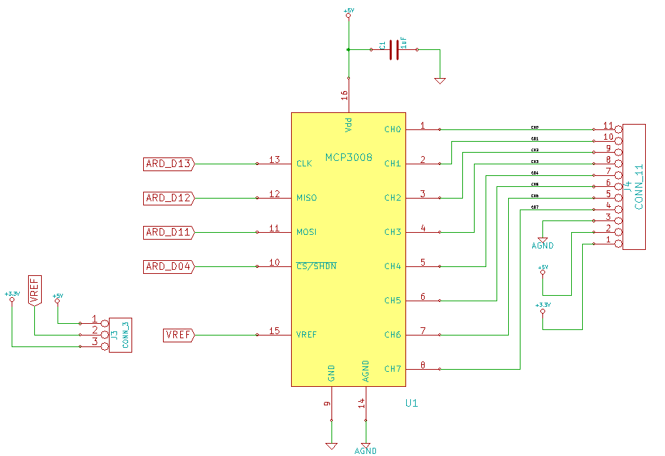
Schematic
Education Shield – MCP3800 ADC Subsystem
Education Shield – Shift Register Subsystem
Setup
For this module, you’ll need the following equipment:
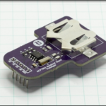
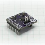
- I2C and SPI Education Shield or the MCP3008 Breakout Board and the Manual Serial Communications Trainer
- Arduino UNO R3
1. Mate the Education Shield with your Arduino UNO R3. If you’re using the MCP3008 Breakout Board and the Manual Serial Communications Trainer, connect 5V to 5V, 3V3 to 3.3V, GND to GND, AGND to GND, CS to Digital4, MOSI to Digital11, MISO to Digital12, and CLK to Digital13 on the MCP3008 board, and then connect 5V to 5V, GND to GND, CLK to Digital6, LAT to Digital7, DAT to Digital8, CLR to Digital9 and OE to Digital5. That’s a lot of pins!
2. Place jumpers on all the 74HC595 Enable jumpers, and use a jumper to select the 5V VREF.
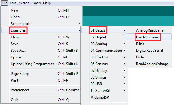
3. Connect your Arduino to your USB cable, and use the Arduino IDE to upload the “Bare Minimum” sketch from the Basics section of the Examples.
Design Criteria
We are going to use the setup from the previous module, including the connection of the potentiometer. As we turn the dial on the pot, we want the LEDs on the face of the I2C and SPI Education Shield to move from right to left. Higher voltages will move the LEDs left, lower voltages will move the LEDs right.
In order to accomplish this, we’ll need to reuse the code from before, and the refreshShiftRegister() function created in the Shift Register education modules. A certain amount of housekeeping will also have to happen in the setup to make sure all the pins are organized, because we’re using a lot of them.
Happily this isn’t at all terribly difficult!
Code Changes
The code from the previous module is pretty well ready to go, we just have to layer in the shift register commands as necessary.
Declarations
Our declarations section is going to expand to include the pins necessary to manage the shift register.
|
1 2 3 4 5 6 7 8 9 10 11 12 13 14 15 16 17 18 19 |
#include <SPI.h> // Include the SPI library SPISettings MCP3008(2000000, MSBFIRST, SPI_MODE0); const int CS_MCP3008 = 4; // ADC Chip Select const byte adc_single_ch0 = (0x08); // ADC Channel 0 const byte adc_single_ch1 = (0x09); // ADC Channel 1 const byte adc_single_ch2 = (0x0A); // ADC Channel 2 const byte adc_single_ch3 = (0x0B); // ADC Channel 3 const byte adc_single_ch4 = (0x0C); // ADC Channel 4 const byte adc_single_ch5 = (0x0D); // ADC Channel 5 const byte adc_single_ch6 = (0x0E); // ADC Channel 6 const byte adc_single_ch7 = (0x0F); // ADC Channel 7 const int oePin = 5; // 74HC595 Output Enable - Active Low const int clockPin = 6; // 74HC595 Clock const int latchPin = 7; // 74HC595 Latch const int dataPin = 8; // 74HC595 Data const int clrPin = 9; // 74HC595 Clear - Active Low |
The “clear” pin exists on the Manual Serial Communications Trainer board, but not on the I2C and SPI Education Shield, so for the Education Shield users, this definition can be omitted as desired.
Setup
As I say above, we need to do some housekeeping in here to bring our board into a ready state for the shift register.
|
1 2 3 4 5 6 7 8 9 10 11 12 13 14 15 16 17 18 19 20 21 22 |
void setup() { SPI.begin (); Serial.begin (9600); pinMode (CS_MCP3008, OUTPUT); digitalWrite (CS_MCP3008, LOW); // Cycle the ADC CS pin as per datasheet digitalWrite (CS_MCP3008, HIGH); pinMode (oePin, OUTPUT); digitalWrite (oePin, HIGH); pinMode (clrPin, OUTPUT); digitalWrite (clrPin, HIGH); pinMode (clockPin, OUTPUT); pinMode (dataPin, OUTPUT); pinMode (latchPin, OUTPUT); refreshShiftRegister (0x00); digitalWrite (oePin, LOW); } |
The SPI setup is as before, and we initiate the serial connection (although we’re not using it this time… old habits). Then we establish the mode and state for the OE and CLR pins. CLR must be driven high, otherwise it will continuously blank out any value we attempt to shift out to the LEDs. We’re going to drive OE high though, just until we’ve blanked the shift register to 0x00, then we’ll bring it low to fully enable the outputs. The only reason for doing this is to prevent the little flicker that might occur when we turn the shift register on, then immediately reset all the LEDs off. Persnickity to be sure, but flickers annoy me.
All the shift register pins are outputs, and after setup is complete, we’ll leave the OE and CLR pins in their respective states: low and high.
refreshShiftRegister()
This code is reused from other modules, and is perfectly good for use here.
|
1 2 3 4 5 6 |
void refreshShiftRegister(byte leds) { digitalWrite (latchPin, LOW); shiftOut (dataPin, clockPin, MSBFIRST, leds); digitalWrite (latchPin, HIGH); } |
This takes the byte input “leds” and shifts it out to the 74HC595 in MSBFirst order. That command is wrapped inside the latch pin management that commits the change to the shift register.
Main Loop
Our main loop dispenses with all the voltage calculations from before, and just does a simple check on the value returned from the ADC. There are 1024 possible values, and we have 8 LEDs to display them on. 1024/8 = 128, so each LED will represent 128 chunks of value. From 0 to 128, we’ll turn on one LED, from 128 to 256, we’ll turn on two LEDs, and so on…
|
1 2 3 4 5 6 7 8 9 10 11 12 13 14 15 16 |
void loop() { int adc_reading = 0; adc_reading = adc_single_channel_read (adc_single_ch7); if (adc_reading <= 128) refreshShiftRegister (0x01); if (adc_reading > 128 && adc_reading <= 256) refreshShiftRegister (0x03); if (adc_reading > 256 && adc_reading <= 384) refreshShiftRegister (0x07); if (adc_reading > 384 && adc_reading <= 512) refreshShiftRegister (0x0F); if (adc_reading > 512 && adc_reading <= 640) refreshShiftRegister (0x1F); if (adc_reading > 640 && adc_reading <= 768) refreshShiftRegister (0x3F); if (adc_reading > 768 && adc_reading <= 896) refreshShiftRegister (0x7F); if (adc_reading > 896 && adc_reading <= 1023) refreshShiftRegister (0xFF); } |
And that’s all there really is to it. It’s not terribly elegant, and I’m sure there are users among you who can find far more creative ways of visualizing the output with fading and chasing and peak levels and such. This is just to get you thinking about the ways we can use the ADC output.
Here’s the full code…
|
1 2 3 4 5 6 7 8 9 10 11 12 13 14 15 16 17 18 19 20 21 22 23 24 25 26 27 28 29 30 31 32 33 34 35 36 37 38 39 40 41 42 43 44 45 46 47 48 49 50 51 52 53 54 55 56 57 58 59 60 61 62 63 64 65 66 67 68 69 70 71 72 73 74 75 76 77 78 79 80 81 82 83 84 85 86 87 88 89 90 91 92 93 94 95 96 97 98 99 100 101 102 103 104 105 106 107 108 109 110 111 112 113 |
/* A sketch to control the 10-Bit, 8-channel ADC MCP3008 on the Rheingold Heavy I2C and SPI Education Shield and output the voltage level as a visual representation using the LEDs on the face of the Education Shield.. The code supposes the use of the Education Shield, but if you're using breakout boards, connect the pins as follows... MCP3008 CS = Digital 4 MCP3008 SCK = Digital 13 MCP3008 MISO = Digital 12 MCP3008 MOSI = Digital 11 MCP3008 5V = 5V MCP3008 3V3 = 3.3V MCP3008 GND = GND MCP3008 AGND = GND Manual Serial Communications Trainer CLK = Digital 6 Manual Serial Communications Trainer LAT = Digital 7 Manual Serial Communications Trainer DAT = Digital 8 Manual Serial Communications Trainer CLR = Digital 9 Manual Serial Communications Trainer OE = Digital 5 Manual Serial Communications Trainer 5V = 5V Manual Serial Communications Trainer GND = GND Website: https://rheingoldheavy.com/mcp3008-tutorial-03-integrating-the-adc-with-the-leds/ Datasheet: http://ww1.microchip.com/downloads/en/DeviceDoc/21295d.pdf */ #include <SPI.h> // Include the SPI library SPISettings MCP3008(2000000, MSBFIRST, SPI_MODE0); const int CS_MCP3008 = 4; // ADC Chip Select const byte adc_single_ch0 = (0x08); // ADC Channel 0 const byte adc_single_ch1 = (0x09); // ADC Channel 1 const byte adc_single_ch2 = (0x0A); // ADC Channel 2 const byte adc_single_ch3 = (0x0B); // ADC Channel 3 const byte adc_single_ch4 = (0x0C); // ADC Channel 4 const byte adc_single_ch5 = (0x0D); // ADC Channel 5 const byte adc_single_ch6 = (0x0E); // ADC Channel 6 const byte adc_single_ch7 = (0x0F); // ADC Channel 7 const int oePin = 5; // 74HC595 Output Enable - Active Low const int clockPin = 6; // 74HC595 Clock const int latchPin = 7; // 74HC595 Latch const int dataPin = 8; // 74HC595 Data const int clrPin = 9; // 74HC595 Clear - Active Low void setup() { SPI.begin (); Serial.begin (9600); pinMode (CS_MCP3008, OUTPUT); digitalWrite (CS_MCP3008, LOW); // Cycle the ADC CS pin as per datasheet digitalWrite (CS_MCP3008, HIGH); pinMode (oePin, OUTPUT); digitalWrite (oePin, HIGH); pinMode (clrPin, OUTPUT); digitalWrite (clrPin, HIGH); pinMode (clockPin, OUTPUT); pinMode (dataPin, OUTPUT); pinMode (latchPin, OUTPUT); refreshShiftRegister (0x00); digitalWrite (oePin, LOW); } void loop() { int adc_reading = 0; adc_reading = adc_single_channel_read (adc_single_ch7); if (adc_reading <= 128) refreshShiftRegister (0x01); if (adc_reading > 128 && adc_reading <= 256) refreshShiftRegister (0x03); if (adc_reading > 256 && adc_reading <= 384) refreshShiftRegister (0x07); if (adc_reading > 384 && adc_reading <= 512) refreshShiftRegister (0x0F); if (adc_reading > 512 && adc_reading <= 640) refreshShiftRegister (0x1F); if (adc_reading > 640 && adc_reading <= 768) refreshShiftRegister (0x3F); if (adc_reading > 768 && adc_reading <= 896) refreshShiftRegister (0x7F); if (adc_reading > 896 && adc_reading <= 1023) refreshShiftRegister (0xFF); } void refreshShiftRegister(byte leds) { digitalWrite (latchPin, LOW); shiftOut (dataPin, clockPin, MSBFIRST, leds); digitalWrite (latchPin, HIGH); } int adc_single_channel_read(byte readAddress) { byte dataMSB = 0; byte dataLSB = 0; byte JUNK = 0x00; SPI.beginTransaction (MCP3008); digitalWrite (CS_MCP3008, LOW); SPI.transfer (0x01); // Start Bit dataMSB = SPI.transfer(readAddress << 4) & 0x03; // Send readAddress and receive MSB data, masked to two bits dataLSB = SPI.transfer(JUNK); // Push junk data and get LSB byte return digitalWrite (CS_MCP3008, HIGH); SPI.endTransaction (); return dataMSB << 8 | dataLSB; } |
Different LED Pattern
Instead of having the bar of LEDs grow to the left, you can also have a single LED move left and right as an indicator.
Replace the if statements with these instead…
|
1 2 3 4 5 6 7 8 |
if (adc_reading <= 128) refreshShiftRegister (0x01); if (adc_reading > 128 && adc_reading <= 256) refreshShiftRegister (0x02); if (adc_reading > 256 && adc_reading <= 384) refreshShiftRegister (0x04); if (adc_reading > 384 && adc_reading <= 512) refreshShiftRegister (0x08); if (adc_reading > 512 && adc_reading <= 640) refreshShiftRegister (0x10); if (adc_reading > 640 && adc_reading <= 768) refreshShiftRegister (0x20); if (adc_reading > 768 && adc_reading <= 896) refreshShiftRegister (0x40); if (adc_reading > 896 && adc_reading <= 1023) refreshShiftRegister (0x80); |


