In Part 1, I broke the schematic down into bite sized subsystems, and here in part 2, I’m going to start digging into the first of those: the Arduino voltage regulator.
Build An Arduino UNO R3 from Scratch Table of Contents
LDO Voltage Regulator Background
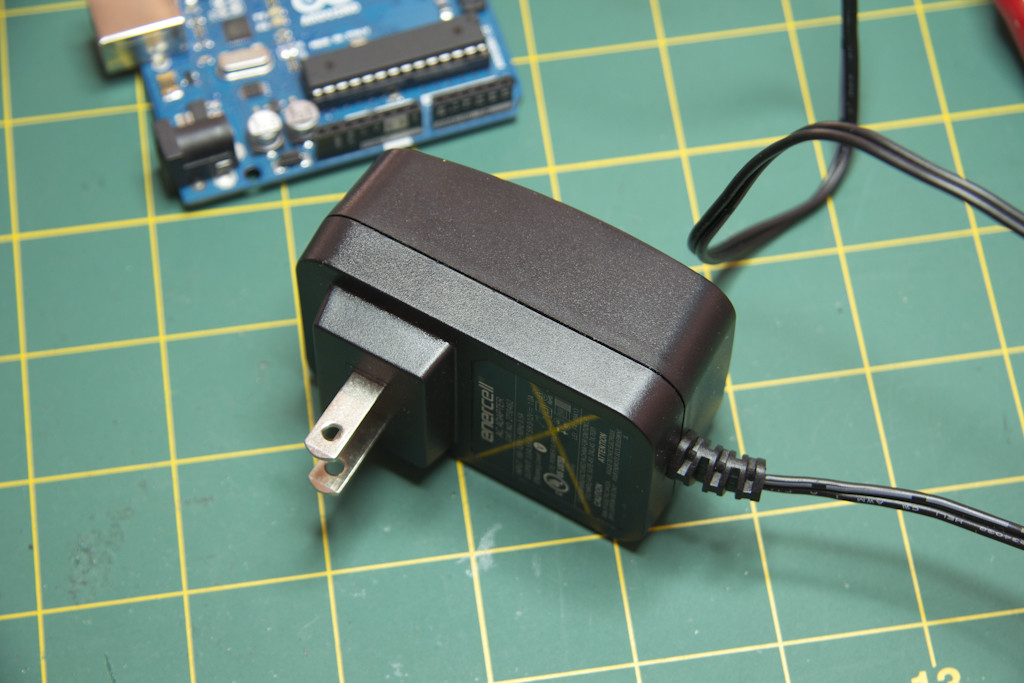
For those unfamiliar with what a voltage regulator does, it takes some input DC voltage, typically from an AC to DC converter in the shape of a black plastic wall wart, and spits out some other, smaller voltage. Ideally, it provides this voltage in a very steady fashion, regardless of any noise that might be present on the input side and regardless of what sort of loads might be connected to the output side. They come in a huge variety of different shapes and sizes and specs, and are probably one of the most purchased active components.
The “LDO” means “Low Drop Out” voltage, meaning that the input voltage can be very, very close to the output voltage. Obviously, you get nothing for free, and the cost of regulating a voltage is part of the voltage itself, so your input value must always be higher than the output value. The spec you’d look for would be the, you guessed it, drop out voltage. There are other important specs like maximum current, Power Supply Rejection Ratio, Ripple Rejection, Quiescent Current and so forth, but the big daddy of LDO specs is the drop out voltage. We’ll deal with the others if they arise during design.
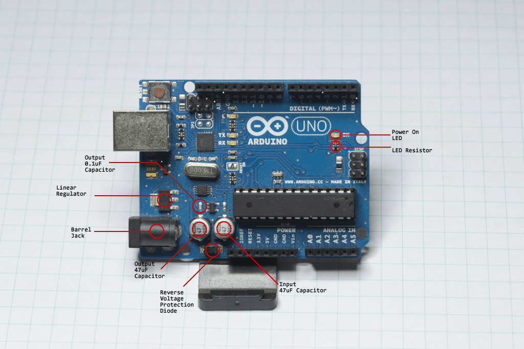
In the end, the whole LDO subsystem is designed to work with voltages supplied through either the DC jack (big plastic thing on the board edge), or through the VIN pin as we’ll see. The voltage you get from the USB cable is entirely a different story.
Voltage Regulator Subsystem Before
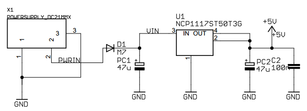
This is how the voltage regulator subsystem appears in the official Arduino schematic…
Over on the left, is a component called “Power Supply” with three pins. That’s the barrel jack you’d plug the wall wart into.
Moving towards the right, there’s a diode, D1, which acts as a reverse voltage protection diode. Wall warts come in two varieties, because God hates us and wants us to blow up our electronics: positive voltage on the outside of the plug and ground in the middle, or ground on the outside of the plug and positive voltage in the middle. I’ll need to confirm it by looking at the datasheet for the barrel jack, but I suspect this is designed to accept a plug with voltage in the middle. If you connect the wrong type, the reverse voltage protection diode will prevent electricity from conducting in the wrong direction, saving your Uno from blowing up (to a certain extent). The designation “M7” on the schematic means it’s a pretty standard 1N4007 rectifier diode, just in a surface mount package.
After passing the diode test, the voltage goes next to the actual linear regulator, U1. It’s listed as an NCP117ST50T3G. I’ve used an NCP1117DT50 before, and don’t know what the difference is between the two, but I suspect they’re very similar, and probably only a physical shape difference between them. Have to look at the datasheet for that.
You’ll see on either side of U1, there are some capacitors: PC1, PC2 and C2. That means “polarized capacitor” 1 and 2, and a regular ceramic capacitor C2. PC1 and PC2 are 47uF and C2 is 0.1uF (100nF). This is a very typical configuration for a fixed voltage regulation circuit. In variable circuits, there are resistors as well, that allow you to customize the output voltage, but since all this cares about is providing super clean 5V, all you see are capacitors. They provide a well of electrical potential that helps to keep the input and output voltages steady. Essentially they’re bypass caps. Big, honkin’, bypass caps. Now why their values are what they are, is something that will probably become clear when consulting the NCP117 datasheet.
Above the two right hand caps, you’ll see the +5V line that becomes the essential power rail for the entire Arduino board. Anywhere you see “+5V” on the schematic, they are all interconnected as a power rail.
The last little thingy on the LDO schematic subsection is a pair of 1K resistors connected in parallel with an LED. This is the LED that turns on when something starts supplying 5V to the board, either through the voltage regulator output or from the USB connection. If the 5V rail is energized somehow, this LED turns on. The two 1K resistors in parallel form an equivalent resistance of 500 ohms (look up basic “resistors in parallel” if you’re not familiar with that calculation), limiting the current to the LED. If you’re wondering “why didn’t they just use one resistor”, well, they had a couple of 1K resistors left over in one of the resistor networks, so rather than spend money on another part, they just used what they had. That’s engineering!
Voltage Regulator Subsystem After
This is what it the LDO subsystem looks like after I’ve drafted the same schematic in KiCad.
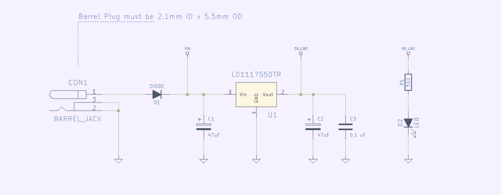 All the parts have been sourced through parts.io, and represent the best compromise as I could achieve between low price and low risk.
BOM (csv): Arduino UNO R3 Clone From Scratch – Voltage Regulation Subsystem
Voltage Regulator Subsystem Parts Selection Notes
Barrel Jack
The very first part I looked for was the barrel jack, labeled as “DC21MMX” on the official schematic. The thing is a unicorn as near as I can tell, doesn’t exist at my purchase level. So I’m going with an alternative 5mm OD / 2.1mm ID barrel jack that I’ve used before from Würth Elektronik. It will be compatible with the majority of wall warts out there, voltage inside, ground outside.
Linear Regulator IC
The next stumbling block was sourcing the linear regulator. The part number that Arduino lists, NCP117ST50T3G, is available, but shows as a high risk component at parts.io, with a risk rank of 3.2. I need to find an equivalent based on the spec, but much lower risk. Using the parts.io search engine and searching for linear regulator ICs, with a dropout voltage max of 1.2V, there is a 5V fixed positive LDO with a risk rank of 2 from ST Micro, the LD1117S50TR. Looking at the specs for the components, it’s pretty much a direct replacement, maybe even slightly better drop out voltage and current handling. In the end, it has to accept up to 15V without question, give me a fixed 5.0V output, get as loooooow a drop out voltage as it can, even at high current, and be able to provide up to 500mA (although that’s well above anything we’d want the uC to try to draw). Ripple rejection and power supply rejection aren’t terribly critical, since the power should be coming in from a generally regulated source already, the wall wart. I know this isn’t guaranteed, but I think we’ll be fine.
Reverse Voltage Protection Diode
The diode is a really standard rectifier diode, low VFORWARD at low current, and since the max current we’ll draw is 500mA or less (hopefully much less) VF won’t ever rise too high. Realistically we’re talking about having to tolerate a reverse voltage of 15V with some sort of potential spike as a multiple of that, if something gets plugged in that shouldn’t be. These cheap recitifier diodes have reverse voltage levels of something like 500V or 800V of either AC or DC, so we should be well good.
Regulator Input/Output Capacitors
Picking the right LDO input and output capacitors was a little tricky. There is no explanation as to why the caps on the Arduino are 47uF in size, and the datasheet for the LD117S50TR doesn’t mention anything other than “10uF should be cool”. The input capacitor just provides a pocket of spare electrons… a bunch of volts that can be drawn on if there’s a momentary dip in the supply. The output capacitor forms a loop with the internal circuitry (covered in excruciating detail in this Texas Instruments AppNote), and the Equivalent Series Resistance (ESR) of the capacitor is the crucial spec — more so than the capacitance value (although I wouldn’t go below the 10uF they list). In the datasheets for the TI and ONSemiconductor equivalent components, they both state that the ESR of the output cap should be between 0.3Ω and 22Ω. My suspicion is the 47uF size isn’t anything special (maybe there was a discount on 47uF caps the day they made the decision to go forward with the design), and all you really have to do is target the correct ESR. I found a nice low risk 47uF cap from Vishay on parts.io, MAL215371479E3, with a 0.5Ω ESR.
