Download: Stripboard Planning Worksheet
I’ve been doing some in depth research on modular synthesizer and Eurorack module designs. As long as people have been making music, they’ve also wanted to do it with instruments they’ve made themselves, and electronic music is no different. What has really surprised me is that most of the Synth DIY designers seem to love working with StripBoard (aka: verboard, busboard, perfboard, protoboard, etc.), rather than designing their own circuit boards. I suppose I was coming at it as an engineer towards music, rather than thinking of it from the viewpoint of a musician that might not have worked with electronics directly before. Imagine all you want to do is create some really crazy oscillators and the keeper at the gates of music says, “Sorry, first you gotta learn an eCAD package”. I can see how that would be a turn off.
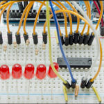
If you’re unfamiliar with stripboard, commonly it’s a piece of phenolic board with copper tracks laid on it in parallel lines, with holes drilled at regular intervals along the track. There are many variations: some follow a breadboard pattern, some are just disconnected plated holes that you bridge with solder blobs, but I’d say the most common is the parallel drilled traces.
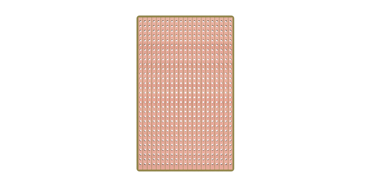
By selectively soldering strips together with hookup wire, and cutting traces at strategic points, you can build out your circuit in a permanent fashion that is electrically conductive and structurally sound.
The problem that I have with stripboard, is that generally, I’m awful at using it. The one thing that really helps me is planning it out on paper first, rather than plopping everything into the board and trusting that I’ll figure it out as I go. There are a number of software packages available to help with that:
- Lochmaster 4.0 (cost €50)
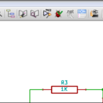
- VeeCAD Stripboard Editor (free / open source)
- Fritzing (free / open source / €8 donation recommended)
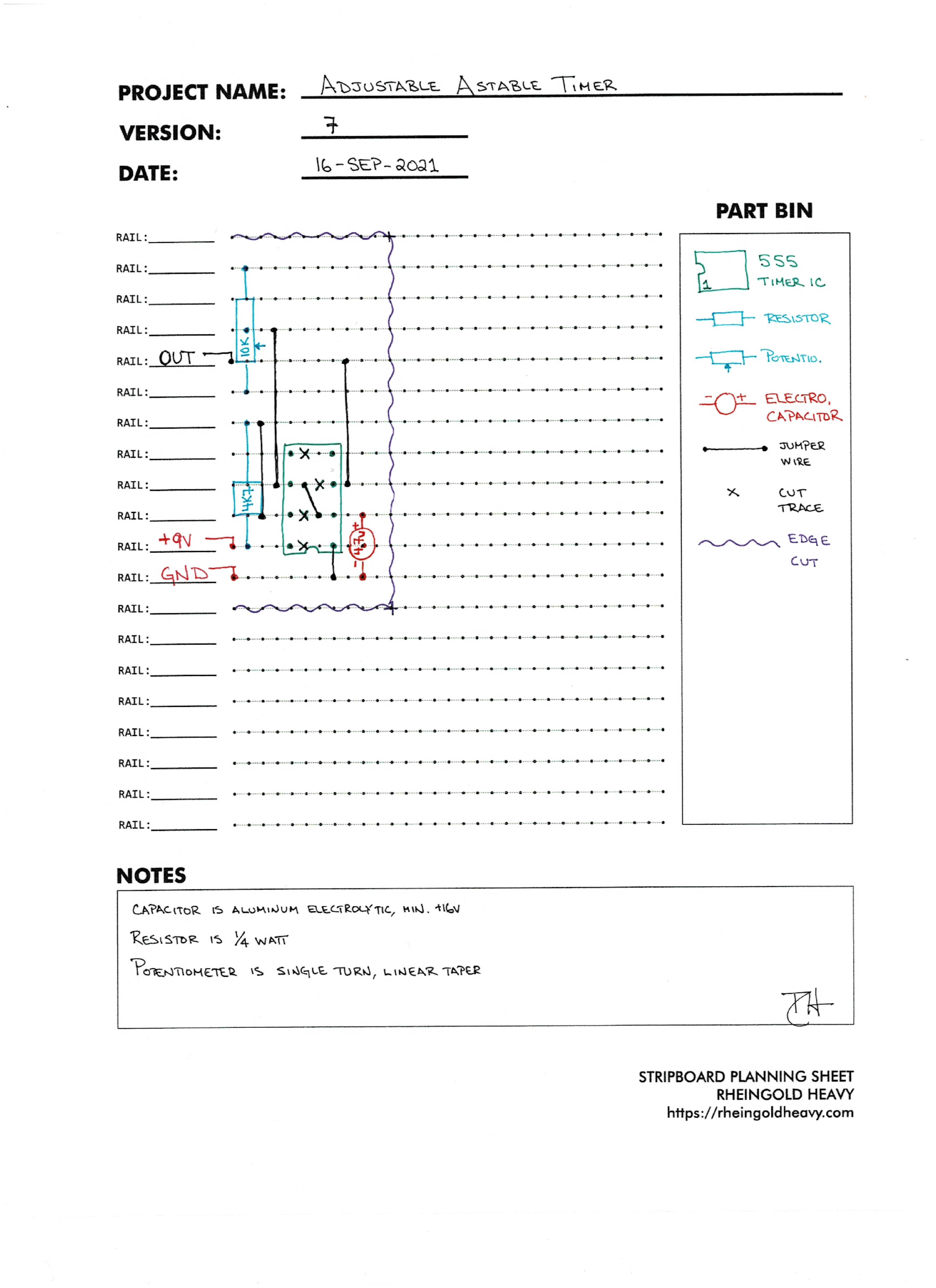
If none of those solutions suits your needs though, I’ve created this worksheet to help with that strip board planning process. The blank is available at this link, Stripboard Planning Worksheet, as a PDF, and I highly encourage you to print out quite a number of them, because you’ll discover that it takes five or six iterations to get even the most simple of designs right. The image below is of a super simple 555 timer with a potentiometer to let you adjust the oscillations, and even this took me a solid five times to layout. (I am way out of practice though, so, that does count against me). If you want to try building something out on strip board, I hope you’ll find this helpful!