In the last module, we achieved a sampling rate of 35khz with the MCP3008 ADC and an Arduino. How fast can we actually get?
Objectives
- Understand the importance of the Nyquist Rate.
- Learn other methods for increasing the speed of your MCP3008 subsystem.
Background
MCP3008 Functionality Overview
Arduino SPI Library
Microchip MCP3008 Datasheet
Schematic
Education Shield – MCP3800 ADC Subsystem
Setup
For this module, you’ll need the following equipment:
- I2C and SPI Education Shield or the MCP3008 Breakout Board
- Arduino UNO R3
1. Mate the Education Shield with your Arduino UNO R3. If you’re using the MCP3008 Breakout Board, connect 5V to 5V, 3V3 to 3.3V, GND to GND, AGND to GND, CS to Digital4, MOSI to Digital11, MISO to Digital12, and CLK to Digital13. That’s a lot of pins!
2. Connect your Arduino to your USB cable, and use the Arduino IDE to upload the “Bare Minimum” sketch from the Basics section of the Examples.
How Fast Do We Need To Be
The first example in the last module showed that 500 samples taken of something that happened over 1800 times isn’t nearly sufficient to genuinely represent the signal that was measured. The problem is even trickier than that. If the signal you’re sampling is sufficiently faster than the speed at which you’re measuring, you can actually generate really solid results, that are absolutely and completely wrong. This is called aliasing… just like an international man of mystery will assume an alias as a disguise, a signal can assume an alias to fool you into thinking it’s something it’s not. Take the really nice 660Hz graph we generated previously. Hidden inside that signal, is another entirely reproducible sine wave, that could have been measured if we were sampling at a slower rate.
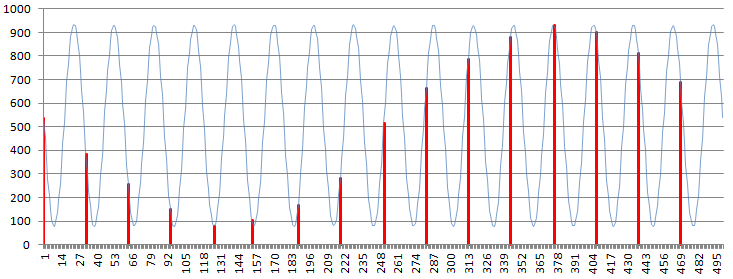
It seems to reason then, that we must always sample at some speed faster than the signal we’re attempting to measure… or rather, we have to sample at some speed faster than the fastest signal we expect to measure. This rate is called the Nyquist Rate, and I’ll just boil it down to “you have to sample twice as fast as the fastest signal you expect to measure”.
This is important to note, that sampling the signal at this rate is useful for frequency detection. We could sample this as a single point in time if we just wanted to know what voltage the signal was at and do that with ease, but in order to detect a frequency, or a frequency change, or record changing frequencies, we have to sample at the speed necessary to verify that we’re getting accurate measurements. Knowing how to increase to that speed will be useful for other usages of the MCP3008 as well though.
Increasing Sampling Speed Further
After isolating the serial commands from our measuring function, we experienced a pretty big performance gain. There are other places we can look to try to cut more fat from the scenario. Let’s have a look at what the adc_single_channel_read function is doing electrically to see what’s taking the most time.
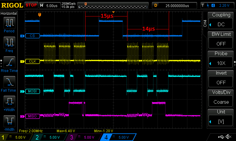
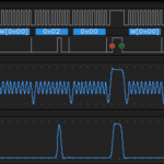
Clock, MISO and MOSI are handled by the ATMEGA328P microcontroller, which is doing all the SPI signaling when it receives the command to do so from the SPI library. Short of increasing the clock frequency to 4Mhz (above the max 3.6Mhz listed in the datasheet), I don’t think we could improve the actual signaling. However, if you measure the time it takes in between each chunk of SPI activity (remember, we’re constantly generating three frames, so what you’re seeing is two runs through the for loop on that scope screen capture), we’re taking 15µs to make up our minds to do some more SPI stuff, which is just as long as it takes to do the SPI stuff in the first place. That’s a TON of time.
|
1 2 3 4 5 6 7 8 9 10 11 12 13 14 15 16 17 18 |
int adc_single_channel_read(byte readAddress) { byte dataMSB = 0; byte dataLSB = 0; byte JUNK = 0x00; SPI.beginTransaction (MCP3008); digitalWrite (CS_MCP3008, LOW); SPI.transfer (0x01); // Start Bit dataMSB = SPI.transfer(readAddress << 4) & 0x03; // Send readAddress and receive MSB data, masked to two bits dataLSB = SPI.transfer(JUNK); // Push junk data and get LSB byte return digitalWrite (CS_MCP3008, HIGH); SPI.endTransaction (); return dataMSB << 8 | dataLSB; } |
Since we’re only dealing with a single chip, it’s configuration never changes. We’re also not turning the SPI bus on and off to release the pins for other purposes, so we don’t really need to beginTransaction and endTransaction every time. Let’s sandwich that around the for loop in setup instead and take it out of the function.
|
1 2 3 4 5 |
SPI.beginTransaction (MCP3008); for (int i = 0; i < 500; i++) { adc_reading [i] = adc_single_channel_read (adc_single_ch7); } SPI.endTransaction (); |
With those commands removed from constant execution, let’s see how fast we are now.
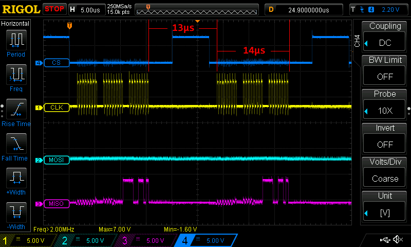
A savings of about 2µs. That’s not too shabby, but there’s a nasty little secret hiding in plain sight.
Digital Write vs. Port Commands
Looking at the scope trace, inside that vast span of no activity the chip select pin goes high and then goes low again. It may or may not be obvious, but what we’re focused on is the end of our function and the start of it again. Assuming the assembly language code that assigns variables to memory spaces, which is what our variable declarations and “return” command are doing, take up only a few 16Mhz clock cycles (and can’t be eliminated anyway), the main thing that’s happening is we’re bringing CS high at the end of the function, but immediately bringing it low again at the start of the function, each time through the for loop, with really nothing to slow it down in between. And yet, the time between the line going high and the line going low is about 7µs, just to toggle the line. In that span of time we can execute nearly one and a half frames of SPI data transfer.
I’m going to execute this code and view it on the oscilloscope.
|
1 2 3 4 5 6 7 8 9 10 11 12 |
int testPin = 8; void setup() { pinMode (testPin, OUTPUT); digitalWrite (testPin, LOW); } void loop() { digitalWrite (testPin, HIGH); digitalWrite (testPin, LOW); } |
All this code does is take a pin and toggle it on and off as fast as the Arduino is capable. I tested every single pin on the Arduino, digital and analog, and measured the speed at which the pin would switch on and off on the oscilloscope.
| Pin Type | Pin Number | Toggle Speed |
|---|---|---|
| Analog | 0 | 94.7kHz |
| Analog | 1 | 94.7kHz |
| Analog | 2 | 94.7kHz |
| Analog | 3 | 94.7kHz |
| Analog | 4 | 94.7kHz |
| Analog | 5 | 94.7kHz |
| Digital | 0 | 88.3kHz |
| Digital | 1 | 88.3kHz |
| Digital | 2 | 88.3kHz |
| Digital | 3 | 69.1kHz |
| Digital | 4 | 88.3kHz |
| Digital | 5 | 71.0kHz |
| Digital | 6 | 71.0kHz |
| Digital | 7 | 88.3kHz |
| Digital | 8 | 88.3kHz |
| Digital | 9 | 73.1kHz |
| Digital | 10 | 67.6kHz |
| Digital | 11 | 69.1kHz |
| Digital | 12 | 88.3kHz |
| Digital | 13 | 88.3kHz |
Even at the fastest switching speed, which was on the analog pins, the fastest we could hope to turn something on and off would have a high period of around 5µs, the ADC CS pin is on Digital 4 which is sort of middle range (being a non-PWM pin), and has a pulse width of 5.4µs.
This is all because of digitalWrite(). The command is very easy to use, easy to understand, but terribly slow on the scale of microcontroller activity. What we need to do, to accelerate the amount of samples we achieve per second, is to bypass the Arduino command and manipulate the pin directly.
Much like the I2C and SPI libraries abstract the direct register manipulation in the back end libraries with very easy to use commands on the front end IDE, the basic command libraries do the same thing.
We can accomplish the same thing that digitalWrite does by using the PORT command. Digital Pin 4 is located in the PORTD register, so we need to toggle the fifth bit (counting from zero) without touching the other bits in the register. To bring the pin low, we use PORTD = PORTD & 0xEF; command. To bring the pin high again, we use PORTD | 0x10;.
Here is a scope trace showing toggling of the ADC CS pin using the digitalWrite technique. Note the frequency of 88.3kHz and pulse width of 5.360µs at the bottom of the trace…
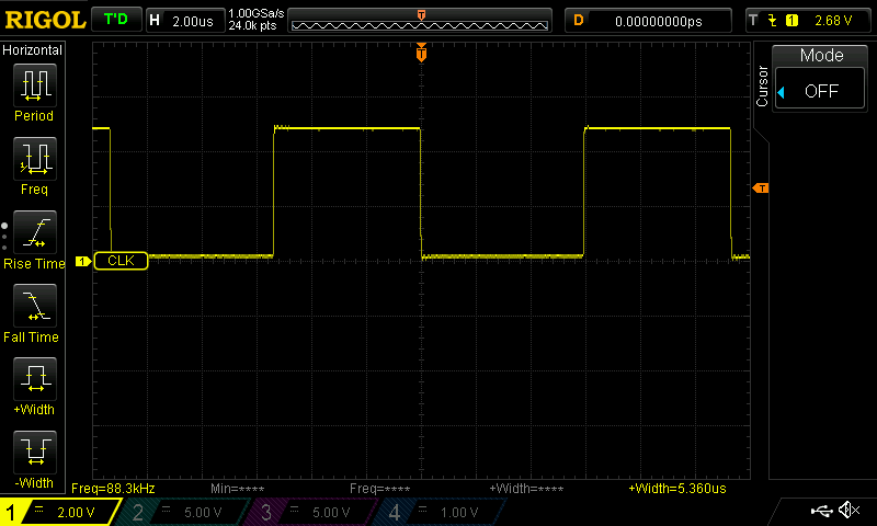
Now here’s the scope trace showing the toggling rate of the same pin using the PORT commands in the main loop. We’ve zoomed way in on the time domain to 200ns per division. The frequency measured is now 1Mhz and the pulse width is 872ns!

The high time seemed a little long to me, and I suspected that was a result of however the main loop is processed. When I placed the port commands into their own for loop, within the main loop (sort of equivalent to a “while (1)” endless loop), the command became much more symmetrical… and over twice as fast again… 2.66Mhz.

With this in hand, we should be able to increase our sampling rate dramatically. Previously, from CS going to low to CS going low took 27µs. By changing to PORT commands, that duty cycle is now 17µs.
That corresponds to 58.8ksps, a sampling frequency of 58.8kHz. Here’s how this has progressed…
- Original Code: 182Hz sampling speed.
- Removed serial commands: 35kHz sampling speed
- Replaced digitalWrite: 58.8kHz sampling speed
This is the graph we had before we moved to the PORT commands…
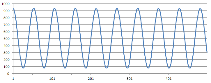
This is the graph we had after we moved to the PORT commands…
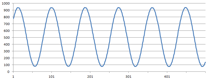
There are half as many periods of the sine wave in the second graph because we’re sampling it almost twice as many times.
Here is the fully optimized code…
|
1 2 3 4 5 6 7 8 9 10 11 12 13 14 15 16 17 18 19 20 21 22 23 24 25 26 27 28 29 30 31 32 33 34 35 36 37 38 39 40 41 42 43 44 45 46 47 48 49 50 51 52 53 54 55 56 57 58 59 60 61 62 63 64 65 66 67 68 69 70 71 72 73 74 75 76 77 78 79 80 81 |
/* A sketch to control the 10-Bit, 8-channel ADC MCP3008 on the Rheingold Heavy I2C and SPI Education Shield at speeds necessary to sample an audio frequency signal. This code specifically uses PORT commands to toggle the ADC chip select pin, instead of using digitalWrite(); The code supposes the use of the Education Shield, but if you're using a breakout board, connect the CS pin to Digital 4, and the SPI pins in their usual locations. Website: https://rheingoldheavy.com/mcp3008-tutorial-05-sampling-audio-frequency-signals-02 Datasheet: http://ww1.microchip.com/downloads/en/DeviceDoc/21295d.pdf */ #include <SPI.h> // Include the SPI library SPISettings MCP3008(2000000, MSBFIRST, SPI_MODE0); const int CS_MCP3008 = 4; // ADC Chip Select const byte adc_single_ch0 = (0x08); // ADC Channel 0 const byte adc_single_ch1 = (0x09); // ADC Channel 1 const byte adc_single_ch2 = (0x0A); // ADC Channel 2 const byte adc_single_ch3 = (0x0B); // ADC Channel 3 const byte adc_single_ch4 = (0x0C); // ADC Channel 4 const byte adc_single_ch5 = (0x0D); // ADC Channel 5 const byte adc_single_ch6 = (0x0E); // ADC Channel 6 const byte adc_single_ch7 = (0x0F); // ADC Channel 7 void setup() { SPI.begin (); Serial.begin (9600); pinMode (CS_MCP3008, OUTPUT); digitalWrite (CS_MCP3008, LOW); // Cycle the ADC CS pin as per datasheet digitalWrite (CS_MCP3008, HIGH); delay(100); int adc_reading[500]; SPI.beginTransaction (MCP3008); for (int i = 0; i < 500; i++) { adc_reading [i] = adc_single_channel_read (adc_single_ch7); } SPI.endTransaction (); for (int i = 0; i < 500; i++) { Serial.println (adc_reading[i]); } } void loop() { } int adc_single_channel_read(byte readAddress) { byte dataMSB = 0; byte dataLSB = 0; byte JUNK = 0x00; //digitalWrite (CS_MCP3008, LOW); PORTD = PORTD & 0xEF; SPI.transfer (0x01); // Start Bit dataMSB = SPI.transfer(readAddress << 4) & 0x03; // Send readAddress and receive MSB data, masked to two bits dataLSB = SPI.transfer(JUNK); // Push junk data and get LSB byte return PORTD = PORTD | 0x10; //digitalWrite (CS_MCP3008, HIGH); return dataMSB << 8 | dataLSB; } |
