Now that we know how to read a single byte of data, the AT25SF081 Reading Memory Tutorial will work to pull back whole pages of data.
Objectives
- Understand how to build a buffer to hold returned data.
- Learn how to craft a function to work with arrays.
Background
AT25SF081 Tutorial 02: Reading Memory Byte
SPI Signals
Adesto AT25SF081 Datasheet
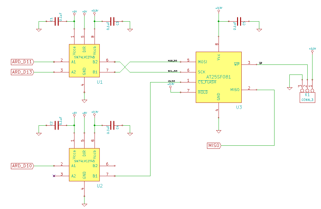
Schematic
Education Shield – AT25SF081 Flash Memory Subsystem
Setup
For this module, you’ll need the following equipment:
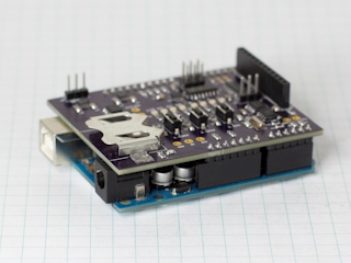
- I2C and SPI Education Shield or the AT25SF081 Flash Memory Breakout Board
- Arduino UNO R3
1. Mate the Education Shield with your Arduino UNO R3. If you’re using the AT25SF081 Flash Memory Breakout Board, connect 5V to 5V, 3V3 to 3.3V, GND to GND, HOLD to Digital09,CS to Digital10, MOSI to Digital11, MISO to Digital12, and CLK to Digital13. That’s a lot of pins!
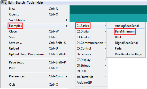
2. Connect your Arduino to your USB cable, and use the Arduino IDE to upload the “Bare Minimum” sketch from the Basics section of the Examples.
Working with the HOLD pin is not necessary for any of the tutorials, it is only included on the breakout board for completeness. In the sketch it will always be set as an output in a high state, and on the I2C and SPI Education Shield, the pin is tied directly to the 3V3 rail on the PCB.
AT25SF081 Reading Memory Pages
Knowing how to pull a single byte of data is great, but since this thing can hold about a million bytes, chances are you’ll want to be able to work with larger quantities of data.
There is no great mystery on how to accomplish this. The AT25SF081 will send you one byte of data at a time, and do so sequentially as long as you keep sending it clock cycles. So if you’re reading the data back from byte 0x000003, you’ll get byte 4, then 5, then 6, etc. in turn as long as you keep sending junk data out on MOSI.
To accomplish this, we’ll need to make three structural changes to our code.
- We’ll need an array of bytes to hold the large chunk of bytes being returned from Flash.
- In order to keep things clean, we’d like to take all the commands necessary to read the data back and place them in their own function. This will also make reusing code much easier for later modules.
- Some method of displaying the returned values will be necessary too, so we’ll need a function to perform that as well.
Building a Buffer
Since we program the memory array in “pages” comprised of 256 bytes each, that seems like a reasonable size to make our buffer, and creating it is simple enough, byte pageData[256];. We now have an array of 256 bytes, ready to receive a full page of data.
You don’t pass the values of arrays back and forth between functions like you do with regular variables, you pass pointers to the array back and forth. That means our the functions that will receive the data and cram it into pageData and the one that will then spit that data out to the serial monitor will have to be coded specifically to accommodate that.
Building Functions
The functions that we need to make I’m going to call readPage and outputData. Nothing too inventive there.
readPage
For the readPage function, we’ll need to send it the starting memory array address to read from, and the pointer to the array we want it to load the data into. The address is called some24bitLocation and the array we declared above, pageData. When the function gets hold of it, the function will reference those as readAddress and memoryData.
|
1 |
void readPage(long readAddress, byte memoryData[]) |
When looking at how we create the function, pay attention to the fact that we’re saying it’s not going to return anything, that’s what the “void” means at the start. We’re passing the pointer to the pageData array and inside the function, we’ll be directly manipulating the values in that array, so there’s nothing to return.
We will still need a junk data byte to use, and the way we send the memory address is exactly the same as in the previous module.
What we need to change is very simple, instead of just reading back the single byte into a variable as we did before, we’re doing to read back single bytes, but do it 256 times in a row, relying on the fact that sending that junk byte over and over again to the AT25SF081 will cause it to read back the next byte, and then the next byte, and then the next byte, etc.
|
1 2 3 |
for (int i = 0; i < 256; i++) { memoryData[i] = SPI.transfer(JUNK); } |
And, of course, all of that has to get wrapped with bringing chip select low and high. The final form of this function then looks like this.
|
1 2 3 4 5 6 7 8 9 10 11 12 13 14 15 16 17 18 19 |
void readPage(long readAddress, byte memoryData[]) { byte JUNK = 0xFF; // Junk data for MOSI output digitalWrite (CS_AT25SF081, LOW); SPI.transfer (OPCODE_SLOWREAD_ARRAY); // Send OpCode SPI.transfer ((readAddress & 0xFF0000) >> 16); // Byte address - MSB Sig Byte SPI.transfer ((readAddress & 0x00FF00) >> 8); // Byte address - MID Sig Byte SPI.transfer ((readAddress & 0x0000FF) >> 0); // Byte address - LSB Sig Byte for (int i = 0; i < 256; i++) { memoryData[i] = SPI.transfer(JUNK); // Read byte from address } digitalWrite (CS_AT25SF081, HIGH); } |
outputData
Our output function is really just a bunch of formatted serial commands. We’ll pass it the pointer to the array just like we did for the readPage function.
|
1 2 3 4 5 6 7 8 9 10 11 12 13 14 15 16 17 18 19 20 21 22 23 24 25 26 27 |
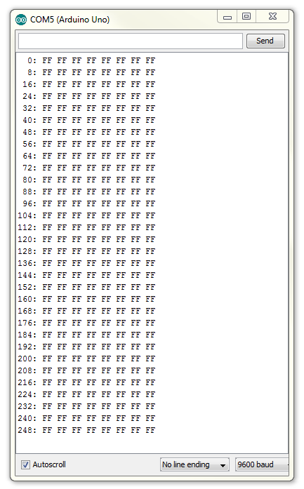
void outputData(byte memoryData[]) { for (int i = 0; i < 256; i = i + 8) { if (i <= 9) Serial.print (" "); if (i > 9 && i < 100) Serial.print (" "); Serial.print (i); Serial.print (": "); Serial.print (memoryData[i], HEX); Serial.print (" "); Serial.print (memoryData[i + 1], HEX); Serial.print (" "); Serial.print (memoryData[i + 2], HEX); Serial.print (" "); Serial.print (memoryData[i + 3], HEX); Serial.print (" "); Serial.print (memoryData[i + 4], HEX); Serial.print (" "); Serial.print (memoryData[i + 5], HEX); Serial.print (" "); Serial.print (memoryData[i + 6], HEX); Serial.print (" "); Serial.println (memoryData[i + 7], HEX); } } |
The if statements at the top just say that if we’re reading back the first 100 bytes of data, add some extra whitespace to the output to the columns nice and clean. When you look at the code and see the output at the same time, it’ll make total sense.
Full Sketch
Here’s the sketch in full…
|
1 2 3 4 5 6 7 8 9 10 11 12 13 14 15 16 17 18 19 20 21 22 23 24 25 26 27 28 29 30 31 32 33 34 35 36 37 38 39 40 41 42 43 44 45 46 47 48 49 50 51 52 53 54 55 56 57 58 59 60 61 62 63 64 65 66 67 68 69 70 71 72 73 74 75 76 77 78 79 80 81 82 83 84 85 86 87 88 89 90 91 92 93 94 95 96 97 98 99 100 101 102 103 104 105 106 107 108 |
/* A sketch to control the 8-Mbit AT25SF081 Flash Memory IC. This sketch will read back a full 256 byte page from the memory address specified in the some24bitLocation variable within Setup. The code supposes the use of the Education Shield, but if you're using a breakout board, connect the CS pin to Digital 10, HOLD to Digital 9, and the SPI pins in their usual locations. Website: https://rheingoldheavy.com/at25sf081-tutorial-03-reading-memory-page Datasheet: http://www.adestotech.com/wp-content/uploads/DS-AT25SF081_045.pdf */ #include <SPI.h> // Include the SPI library SPISettings AT25SF081(8000000, MSBFIRST, SPI_MODE0); // Sets the pin values for the AT25SF081 and MCP3008 const int CS_AT25SF081 = 10; // Flash Memory Chip Select - Active Low const int holdPin = 9; // HOLD Pin - Active Low // Set bits for the various Flash IC OpCodes (see datasheet) const byte OPCODE_SLOWREAD_ARRAY = (0x03); // Memory read up <= 50Mhz (see datasheet) const byte OPCODE_FASTREAD_ARRAY = (0x0B); // Memory read up <= 85Mhz (see datasheet) void setup() { Serial.begin(9600); SPI.begin(); // Set the pin modes pinMode (CS_AT25SF081, OUTPUT); pinMode (holdPin, OUTPUT); // Initialize the device for it's first interaction. digitalWrite (holdPin, HIGH); digitalWrite (CS_AT25SF081, LOW); digitalWrite (CS_AT25SF081, HIGH); long some24bitLocation = 0x0FE8FF; // Starting address we'll read from byte pageData[256]; // Array of bytes to hold a page of data SPI.beginTransaction (AT25SF081); readPage (some24bitLocation, pageData); SPI.endTransaction (); outputData (pageData); } void loop() { } void readPage(long readAddress, byte memoryData[]) { byte JUNK = 0xFF; // Junk data for MOSI output digitalWrite (CS_AT25SF081, LOW); SPI.transfer (OPCODE_SLOWREAD_ARRAY); // Send OpCode SPI.transfer ((readAddress & 0xFF0000) >> 16); // Byte address - MSB Sig Byte SPI.transfer ((readAddress & 0x00FF00) >> 8); // Byte address - MID Sig Byte SPI.transfer ((readAddress & 0x0000FF) >> 0); // Byte address - LSB Sig Byte for (int i = 0; i < 256; i++) { memoryData[i] = SPI.transfer(JUNK); // Read byte from address } digitalWrite (CS_AT25SF081, HIGH); } void outputData(byte memoryData[]) { for (int i = 0; i < 256; i = i + 8) { if (i <= 9) Serial.print (" "); if (i > 9 && i < 100) Serial.print (" "); Serial.print (i); Serial.print (": "); Serial.print (memoryData[i], HEX); Serial.print (" "); Serial.print (memoryData[i + 1], HEX); Serial.print (" "); Serial.print (memoryData[i + 2], HEX); Serial.print (" "); Serial.print (memoryData[i + 3], HEX); Serial.print (" "); Serial.print (memoryData[i + 4], HEX); Serial.print (" "); Serial.print (memoryData[i + 5], HEX); Serial.print (" "); Serial.print (memoryData[i + 6], HEX); Serial.print (" "); Serial.println (memoryData[i + 7], HEX); } } |
After uploading that, open up serial monitor to see the output. Remember since all the function calls are occurring in Setup, they’ll only be executed once.
