I have discovered that I learn best when I build a circuit, and then measure the hell out of it. So, fittingly enough, the first entry in my lab notebook, involves the most basic of circuits every beginner ever builds…
- A voltage source
- An LED
- A current limiting resistor
- A ground reference
In this case, we’ll use 5V (conveniently provided by the +5V pin on an Arduino), a regular every day red 5MM LED, some junky old resistors from a RadioShack Resistor Kit and the ground from our voltage source (again, conveniently provided by one of the GND pins on an Arduino).
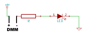
The schematic for this circuit is as simple as they get…

What we’re going to do is assemble the circuit on a breadboard, and then measure it at every point for voltage and then for current draw. By only changing one component, the resistor, between measurements, we’ll be able to see the effect of the resistor on the circuit as a whole. Since we also know a little bit of the math involved, we should be able to predict before hand our measured results.
If you’d like some greater detail on the hands on aspects of measuring this circuit, I wrote a post to work hand in hand with this one, called, using your multimeter.
Let’s start off with measuring our LED… or rather, let’s start by finding some information out about the LED in question. As is covered in far better detail here, here and here, we basically need to know how much voltage we have to stab this thing with to get it to turn on, how much current we can pump through it before it will wink out of existence and how much current we should really be putting through it. The stabbing voltage is called “Forward Voltage”, the maximum current is called, well, Maximum Current, and the “should really be putting through it current” is usually called “typical”. I’m using a plain dumb red 5mm LED that I got as a package of a billion from SparkFun for a project. According to the LED’s datasheet, it has a forward voltage between 1.8 and 2.2V, a maximum current of 30mA and a (I’m not even kidding here) “suggestion using current” of 16-18mA. We’re going to be using a 5V voltage source (5 is more than 2.2) and we’re going to stick that resistor in there to make sure our current doesn’t go above 30mA.
Now for some math…
Basic Ohm’s Law: V = I x R
- “V” is our supply voltage, 5V minus the roughly 2.0V forward voltage of the LED.
- “I” is our maximum current of 0.03 Amps (30 milliamps).
- “R” we don’t know. When calculated, it will be the resistance necessary to bring us in at that maximum.
So, we do some basic algebra, divide both sides by “I” to solve for “R” and we have R = V / I. Plug in our numbers and it’s R = 3V / .03A = 100 Ω. This is the least amount of resistance we can use, without risking immediate destruction of our LED.
But that’s pushing it. Let’s figure out what value we should actually be using to get into the typical range of 16-18mA. R = 3V / .016A = 187.5Ω. This isn’t a standard resistor value, so let’s round up to 220. (180 is a standard resistor value, but since we’re trying to limit current, it’s better to round up instead of down).
We’ll start with that 220Ω resistor in our circuit, but we’ll also see what happens when we build the circuit with other values: 470Ω, 2.2kΩ and 10kΩ.

Voltage is measured by placing the probes of your multimeter in parallel with the circuit, as in the diagram on the left. We’ll call our measuring points the following…
- Vs = Source voltage
- Vf = LED Forward Voltage
- GND = black multimeter lead connection point
You measure the current by placing the multimeter’s probes in series with the circuit. For example, here is the location I placed the probes for my meter to measure the current flow. Notice that the +5V now has to pass through the multimeter before it can get to the resistor. The value read by the DMM will be “I”, the current flow.
With the circuit hooked up, the red LED glows happily as though it didn’t know that I’m the guy that’s in charge of it’s well being. Here’s where it gets interesting. Let’s compare the numbers we came up with, against the ACTUAL numbers we measure…
| Measurement | Vs | Vf | R | I |
|---|---|---|---|---|
| Calculated | 5.00 | 2.00 | 220 | 0.014 |
| Measured | 4.88 | 1.95 | 217 | 0.013 |
Our measurements confirm what we calculated earlier. Of course, the numbers are a little off. The voltage from the Arduino 5V supply is a little low, the forward voltage of the LED is right in the expected range though, and the resistor has a gold band, meaning it should be within 5% of it’s nominal value (it is) and the measured current is within 1 mA of what we expected. (If you do the math to solve for “I” using the measured values of Vs, Vf and R, you actually wind up at 0.0135). In addition to components that aren’t exactly high end, my multimeters are exquisitely cheap, so their accuracy is definitely in question. We’re only off by about 5% at worst, though, so I can accept that.
Now, let’s swap in some different values of resistors and see what the end result is…
| Measurement | Vs | Vf | R | I |
|---|---|---|---|---|
| 470Ω Calculated | 5.00 | 2.00 | 470 | 0.006 |
| 470Ω Measured | 4.88 | 1.89 | 457 | 0.006 |
| 220Ω Calculated | 5.00 | 2.00 | 2200 | 0.001 |
| 220Ω Measured | 4.88 | 1.79 | 2140 | 0.001 |
| 10K Calculated | 5.00 | 2.00 | 10000 | 0.0003 |
| 10K Measured | 4.88 | 1.72 | 10010 | 0.0003 |
Pretty accurate, eh? And as you can imagine, the LED dimmed in brightness as the resistance increased. The only thing that seems strangely off, is the forward voltage. Why is that? Well, the voltage drop of the LED isn’t constant, it can change depending on the current, and as we increase the value of the resistor, we’re making a HUGE change in the current: 14mA at 220Ω to .3mA at 10K. Having a hard time grasping those values? Imagine you had $14.00, then I swap out the resistor and now you have 30 cents. The key here is this excerpt from one of the tables in the datasheet…

What that’s saying, is that when the current flowing through the LED is 20mA, you can expect a forward voltage between 1.8V and 2.2V. If you go outside the bounds of that test condition, all bets are off. Fortunately, not all datasheets are equal, and if we were using a different LED, like the Kingbright WP9294SEC-J3, you would be able to find the following chart in the datasheet…

With this LED, once you hit a current of about 10mA, the forward voltage doesn’t change very much, from 10ma to 15mA the change in forward voltage is something like 60mV just eyeballing the chart. But if you go the other direction, from 10mA to 5mA the forward voltage drops 100mV. If the el cheapo LED from SparkFun reacts at all like the Kingbright (and I have no reason to believe it wouldn’t), you can see that the change in current, as we choke down that pipe with higher and higher resistance, results in a reduction in forward voltage.
If you use the measured values for Vs-Vf and divide it by the measured value of R, you wind up calculating the current to a value that matches out to three decimal places.
| Measurement | Vs Measured | Vf Measured | R Measured | I Measured | I Calculated |
|---|---|---|---|---|---|
| 220Ω | 4.88 | 1.95 | 217 | 0.0130 | 0.0135 |
| 470Ω | 4.88 | 1.89 | 457 | 0.0064 | 0.0065 |
| 2200Ω | 4.88 | 1.79 | 2140 | 0.0014 | 0.0014 |
| 10K | 4.88 | 1.72 | 10010 | 0.0003 | 0.0003 |