I spent some time writing about the theory behind shift registers like the 74HC595, now it’s time to write a little bit about how to use them. Consider this your Shift Register Circuit Build 101 class 🙂 My actual lab notebook has seven laboriously handwritten pages about shift registers in it – hopefully I’ll be able to condense it down a little bit here.
Building a Shift Register Circuit
Here is a basic schematic showing how a 74HC595 is connected to common components.
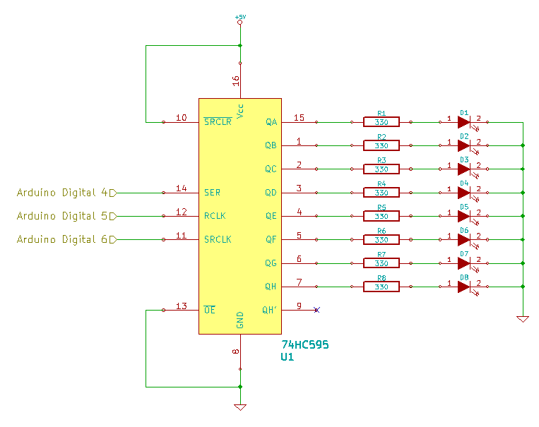
To build that circuit, you only need the following components.
- 1 x 74HC595 Shift Register
- 1 x Arduino Uno R3
- 8 x Red 5mm LEDs
- 8 x 330Ω resistors (1/4 watt is fine)
- Jumper wires to connect it all.
When you’re looking at the schematic, there are a couple things you should note.
First, the pins are arranged out of order around the box, in order to make drawing the thing a little be easier, particularly note that the first output, Pin 15, is on the right and at the top. Only the silicon warlocks that design these things know why they arrange the pinouts the way they do.
Second, the +5V and GND are intended to be the 5V and GND connections on the Arduino.
Third, you’ll see the bar above the OE (Output Enable) and SRCLR (Shift Register Clear), that means they are both active low – they need to be taken to 0V in order for them to do what their name says – and since we want the thing to turn on and do what we tell it to do, we tie them to GND and 5V respectively.
After it’s all hooked up, my breadboard looks like this…
[masterslider id=4]
Man, those spindly little RadioShack resistors look pathetic. To get them into the breadboard I sometimes have to use a pair of bent nose pliers to keep the leads from crumpling outright. Anywho… fantastic… so what does it do? Well, we are going to need a little bit of code uploaded to the Arduino to see what’s going on, so copy the following into the Arduino IDE and push it to your Uno.
Brute Force Shift Register Control
|
1 2 3 4 5 6 7 8 9 10 11 12 13 14 15 16 17 18 19 20 21 22 23 24 25 26 27 28 29 30 31 32 33 34 35 36 37 38 39 40 41 42 43 44 45 46 47 48 |
/* Basic Sketch To Control a 74HC595. https://rheingoldheavy.com/shift-register-circuit-build-101/ */ // Set the pin connections from the shift register int dataPin = 4; int latchPin = 5; int clockPin = 6; void setup() { pinMode(latchPin, OUTPUT); pinMode(dataPin, OUTPUT); pinMode(clockPin, OUTPUT); } void loop() { // Brute Force Method 01 digitalWrite (clockPin, LOW); digitalWrite (dataPin, LOW); // Clock in a single ONE digitalWrite (latchPin, LOW); digitalWrite (dataPin, HIGH); digitalWrite (clockPin, HIGH); digitalWrite (clockPin, LOW); digitalWrite (dataPin, LOW); digitalWrite (latchPin, HIGH); delay (500); // Clock in seven ZEROS for (int i = 0; i < 7; i++) { digitalWrite (latchPin, LOW); digitalWrite (clockPin, HIGH); digitalWrite (clockPin, LOW); digitalWrite (latchPin, HIGH); delay (500); } } |
I call this code “Brute Force” because this has got to be the least elegant and most forceful way of making a shift register do anything. It’s also the most basic. The code sets up the pins for the Data, Clock and Latch and sets them as outputs. Then it performs the arduous task of clocking individual bits into the shift register: take the latch low, bring the clock high then bring the clock low, then take the latch high. If during that sequence, the data was low when clock was high, then a ZERO was sent to the 595. Alternatively, if data was high when clock was high, then a ONE was sent to the 595. In this code, a single ONE is sent out, then seven ZEROS are clocked out (the only concession to efficiency I used was to put the ZEROS in a FOR loop, just so the code wouldn’t take up half the page.) The end result is, a single LED moves majestically from right to left (from QA to QH).
You can play around with this by copying the code for either the ONE or the ZERO, and modifying the FOR loop, to get different patterns to chase across the eight LEDs. It will make the most sense if you limit the amount of clock cycles in the LOOP{} to eight though, and remember the 595 isn’t resetting each time you upload to the Arduino, so it will take a full 8 hand coded clock cycles for your old pattern to be fully shifted out.
Turns out there is a far more efficient way of doing this.
shiftOut()
Instead of manually doing all the clocking, the Arduino has a method called shiftOut(). This allows you to send a whole byte to the Shift Register with a single command. Change your loop to the following…
|
1 2 3 4 5 6 7 8 9 |
void loop() { // Brute Force Method 02 digitalWrite (latchPin, LOW); shiftOut (dataPin, clockPin, MSBFIRST, B10101010); digitalWrite (latchPin, HIGH); } |
Now the output will be four LEDs on with one LED off in between each. The pattern of lit LEDs matches the pattern of 1’s and 0’s in that binary number, and we use the shiftOut() command to tell the Arduino which pins belong to the data and clock and which direction we want to shift things (MSBFIRST), then we give it all 8-bits at once. Remember, the latch has to be cycled low / high in order for the new set of bits to be committed from the shift register to the storage register.
It may not seem like any shifting is going on, but that’s only because instead of sending in individual bits as we did in Brute Force 01, now we’re sending in eight at a time, so the shift register has all of its bits shifted out with each command and, further, it has the same 8 bits shifted in. None too interesting. So change the loop again so it looks like this…
|
1 2 3 4 5 6 7 8 9 10 11 12 13 14 15 |
void loop() { // Brute Force Method 02 digitalWrite (latchPin, LOW); shiftOut (dataPin, clockPin, MSBFIRST, B10101010); digitalWrite (latchPin, HIGH); delay (500); digitalWrite (latchPin, LOW); shiftOut (dataPin, clockPin, MSBFIRST, B01010101); digitalWrite (latchPin, HIGH); delay (500); } |
When you upload that, your circuit should start blinking incessantly. Annoyingly some might say. Whatever pattern of eight 1’s and 0’s you put in there, will be what the Arduino tells the Shift Register to display.
Bit Banging
There’s another way to move the bits around that falls squarely in the lethargic category for things like this, bitSet() and bitClear(). By creating a byte variable (byte variables being 8-bits in length, perfect for things like B10101010), you can then set and clear it’s bits directly using those two commands.
I’ve shortened up the pattern to save room, so this code will only toggle the middle two LEDs on and off. Note in the code that the bitSet and bitClear functions are base 0, not base 1, so to toggle the 4th and 5th LED, you set and clear bits 3 and 4.
|
1 2 3 4 5 6 7 8 9 10 11 12 13 14 15 16 17 18 19 20 21 22 23 24 25 26 27 28 29 30 31 32 33 34 35 36 37 38 39 40 41 42 43 44 45 46 |
/* Basic Sketch To Control a 74HC595. https://rheingoldheavy.com/shift-register-circuit-build-101/ */ // Set the pin connections from the shift register int dataPin = 4; int latchPin = 5; int clockPin = 6; // Create a variable to hold the 8-bit pattern for the leds byte leds = 0; void setup() { pinMode(latchPin, OUTPUT); pinMode(dataPin, OUTPUT); pinMode(clockPin, OUTPUT); } void loop() { // Brute Force Method 03 bitClear (leds, 3); bitSet (leds, 4); refreshShiftRegister (); delay (125); bitClear (leds, 4); bitSet (leds, 3); refreshShiftRegister (); delay (125); } void refreshShiftRegister() { digitalWrite (latchPin, LOW); shiftOut (dataPin, clockPin, MSBFIRST, leds); digitalWrite (latchPin, HIGH); } |
In addition to using bitSet and bitClear, I’ve now placed all the shifting into it’s own function, refreshShiftRegister(), which makes the whole latching and shifting thing easier to perform.
Now this opens up the ability to do some pretty interesting things. For example, using a for loop, you can implement what we did way back in the beginning in a way that is far more elegant…
|
1 2 3 4 5 6 7 8 9 10 11 |
void loop() { // Elegant Method 01 for (int i = 0; i < 8; i++) { bitSet (leds, i); if (i > 0) bitClear (leds, i-1); if (i == 0) bitClear (leds, 7); refreshShiftRegister (); delay (500); } } |
The nice thing is, that it doesn’t have to be a binary value that you pass to shiftOut(), which was a massive revelation to me. You can send the decimal equivalent as well, and get the same result! More on that in the next lab notebook entry.
Click here for the files associated with this post at the Rheingold Heavy GitHub repo.
