When I was going through and comparing the values I was passing the shift register, I wondered if instead of sending a binary value like B00110101, I could send the decimal equivalent, 53, instead, and it turns out that works too. Any number < 256 is consequently an 8-bit number that can be plunked into a shift register for output.
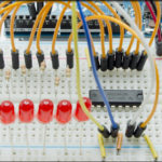
The first thing to try is to see if we can see a visual representation of this by having the shift register light up an LED pattern, equivalent to a binary number. So, if we pass it the number in the left hand column, we should expect to see the pattern of 1’s and 0’s to the right. Here are the first six numbers: 0 – 5…
| Decimal | Bit-8 | Bit-7 | Bit-6 | Bit-5 | Bit-4 | Bit-3 | Bit-2 | Bit-1 |
|---|---|---|---|---|---|---|---|---|
| 0 | 0 | 0 | 0 | 0 | 0 | 0 | 0 | 0 |
| 1 | 0 | 0 | 0 | 0 | 0 | 0 | 0 | 1 |
| 2 | 0 | 0 | 0 | 0 | 0 | 0 | 1 | 0 |
| 3 | 0 | 0 | 0 | 0 | 0 | 0 | 1 | 1 |
| 4 | 0 | 0 | 0 | 0 | 0 | 1 | 0 | 0 |
| 5 | 0 | 0 | 0 | 0 | 0 | 1 | 0 | 1 |
Simple enough, just change the loop() code we were using in Build 101 to the following code…
|
1 2 3 4 5 6 7 8 9 10 11 12 |
void loop() { // Binary Counter for (byte i = 0; i < 256; i++) { leds = i; refreshShiftRegister (); delay (500); } } |
Tada! You’ve just created the electronic equivalent of drying paint. While that isn’t a particularly interesting thing for a shift register to do, it does demonstrate the correlation between the inputting of a decimal number, and the outputting of it’s binary equivalent. You can actually change the value of the upper bound of the for loop to B11111111 or 0xFF and the program runs exactly the same, I just like looking at decimal numbers… they make more sense at this point.
So moving on from here, let’s have a look at the two pins that we sort of discarded as semi-dangerous in the original schematic: OE, “Output Enable” and SRCLR, “Shift Register Clear”.
OE drives the outputs to a high impedance state and it’s either full on or full off, no in between. However, it is susceptible to the tender ministrations of a PWM signal from the PWM capable Arduino pins, so you can effectively dim LEDs on the outputs this way.
SRCLR wipes out the contents of the shift register, so by bringing SRCLR low and toggling the latch, you clear it for new incoming data. I imagine this is far more important if you’re banging bits in one at a time and you want to make sure you don’t shift useless data over a bit or two by accident. If you’re constantly using BYTES and updating all 8 bits at a time, this doesn’t really matter much since you can do the same thing in code by sending B00000000.
Just a reminder, OE and SRCLR are active low, so you pull the pin to GND in order to get what their name describes. That’s what the bar over the word means.
Incidentally, the bar over the letters is referred to as a “Macron”. And that means that instead of just typing “OE” to display this pretty text for you, I have to replace it with this mess everytime I type it.
<span style="text-decoration:overline">OE</span>
You should be grateful.
Anyway, my detestation of span styles and HTML escape characters aside, let’s play with these two pins. First, we need to modify the schematic…
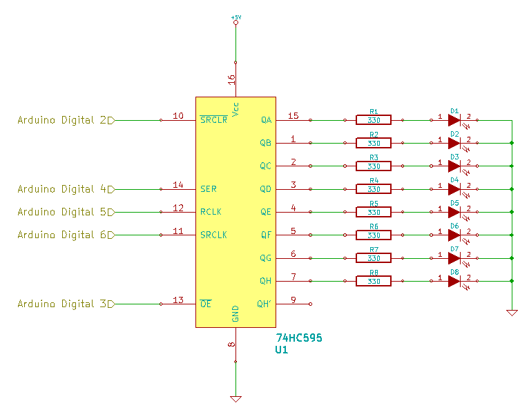
Essentially, we’re just disconnecting Output Enable and Clear from their direct power and ground rail tie-ins and connecting them to Arduino pins instead. Additionally, we’re ensuring that Output Enable is connected to a PWM capable pin.
|
1 2 3 4 5 6 7 8 9 10 11 12 13 14 15 16 17 18 19 20 21 22 23 24 25 26 27 28 29 30 31 32 33 34 35 36 37 38 39 40 41 42 43 44 45 46 47 48 49 50 51 52 53 54 55 56 57 58 59 60 61 62 63 64 65 66 67 68 69 70 71 72 73 74 75 76 |
/* Basic Sketch To Control a 74HC595. Using the OE and SRCLR pins. https://rheingoldheavy.com/shift-register-circuit-build-102/ */ // Set the pin connections from the shift register int clearPin = 2; int enablePin = 3; int dataPin = 4; int latchPin = 5; int clockPin = 6; // Create a variable to hold the 8-bit pattern for the leds byte leds = 0; void setup() { pinMode(latchPin, OUTPUT); pinMode(dataPin, OUTPUT); pinMode(clockPin, OUTPUT); pinMode(clearPin, OUTPUT); pinMode(enablePin, OUTPUT); digitalWrite(enablePin, LOW); digitalWrite(clearPin, HIGH); } void loop() { // Blink the display three times using SRCLR pin for (int i = 1; i < 4; i++) { leds = 255; refreshShiftRegister(); delay(250); clearShiftRegister(); delay(250); } // Turn all the LEDs on so they can be faded leds = 255; refreshShiftRegister(); // Fade the LEDs by using PWM on the OE pin int x = 1; for (int j = 0; j > -1; j = j + x) { analogWrite(enablePin, j); if (j == 255) x = -1; delay(10); } digitalWrite (enablePin, LOW); } void refreshShiftRegister() { digitalWrite (latchPin, LOW); shiftOut (dataPin, clockPin, MSBFIRST, leds); digitalWrite (latchPin, HIGH); } void clearShiftRegister() { digitalWrite (latchPin, LOW); digitalWrite (clearPin, LOW); digitalWrite (latchPin, HIGH); digitalWrite (clearPin, HIGH); } |
This code will blink all the LEDs three times, then take them from full brightness to off to full brightness again. The blinking uses a new function called clearShiftRegister() that cycles the latch while the Clear pin is low, wiping the output. So while it’s blinking, the LED’s off is a representation of B00000000. The fading uses the Output Enable pin and PWM / analogWrite to vary the length of time the pins are driven to high impedance. In a high impedance state, no current flows to the LEDs and they turn off, and we’re only varying the length of off time to make it look like they fade out and fade in again. Pretty neat.
The fading of the LEDs is useful if you want to do something pretty with lighting and a shift register, but in reality, using SRCLR in code doesn’t really make much sense, because you can wipe out the value of the shift register much more quickly by just sending it a bunch of zeros instead. The Clear pin makes much more sense if you tie it to some external source that causes it to blank the shift register for reasons other than your code, like using a mechanical switch to reset the display, or a signal from some sensor energizing the base of a transistor that drives the Clear pin to ground. Doing it in code seems inefficient.
Click here for the files associated with this post at the Rheingold Heavy GitHub repo.
