I wanted to provide some more visual references on exactly how and where you can hook up a multimeter to perform basic circuit measurement with the various parts of the LED circuit. It can be a little daunting, even with so few components to know where to put the probes to get something useful back. When you get the hang of it though, it really starts to open up your understanding of what’s happening in any particular circuit. (I am writing this believing that you, the reader, have some working knowledge of how to setup your multimeter in the first place, in terms of putting the test leads into the correct sockets, and setting it to read voltage, resistance or current.)
Like I said in the basic LED circuit page, if I haven’t measured it, I don’t understand it – if I can’t make a change to something and be able to predict what the outcome of that change is, then I really don’t grasp what’s happening.
Let’s take that basic circuit again and have a look at it…
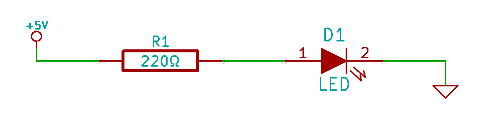
There are three places I can see where we’d want to try to measure the voltage:
- Left of the resistor. This will tell you what level your voltage source is at.
- Between the resistor and the LED. This will tell you how much voltage is trying to push across the LED, which, coincidentally, is called the “Forward Voltage” of the LED.
- After the LED. Really just to confirm that your multimeter shows “0V”. Why? Because I measure everything.
We can also measure the actual resistance of “R”, and the current draw of the circuit, but we’ll need to disassemble parts of it in order to do that.
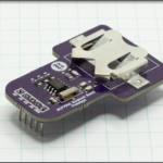
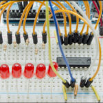
Let’s have a look at the parts that we’re going to be playing with…
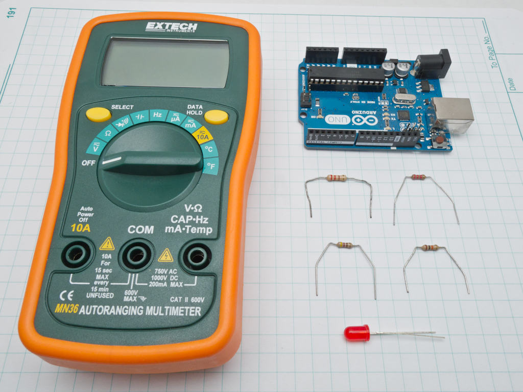
What we have here is an Arduino Uno that will supply 5V and a Ground reference, a simple 5MM red LED, four different values of resistors, and one of my multimeters.
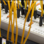
The first things we’re going to measure, are the resistance values of those four little dudes. The color banding on them (which I assure you I will never memorize) has them at 220Ω, 470Ω, 2200Ω and 10000Ω (I’m going to stop using that full notation, and start using the generally accepted shorthand of 220, 470, 2K2 and 10K). All of them are rated at 5% tolerance, so I’m fully expecting some deviation. Now, it’s easy enough to hold those things in your hand and pinch the probe tips against them to get the actual value, but doing that you wind up with no hands left to write with. Consequently, I like doing this in my breadboard. To make it easier, I have some special test lead tips I bought at RadioShack. Basically you slide your multimeter leads into one end to convert it into a pin that fits standard breadboard positions. Probably the single most useful thing I’ve bought besides a decent soldering iron. Once you note down the reading on your multimeter, you can just swap out the resistor one to the next to the next and go back and take notes. When you’re looking at the values in these photos, note that this multimeter is autoranging, so you’ll have to look closely at whether it’s .2148, 214.8 or 2.148K.
[masterslider id=1]If you properly design test points into PCBs, this technique works just as well. Hook the test leads into the test points and you can do hands free evaluation of circuit output without having to do the chopstick-multimeter-probe-hold as you fiddle with a trim pot.
Now that we’ve got the value of our resistors, we can go on to start measuring the voltage in the circuit. We have three test points and four different resistor values, making twelve total measurements that we’d have to take. The Basic LED Circuit post has the details on those measurements, I’ll just show you how I position everything using the first resistor here.
Your black lead can be placed either at the cathode of the LED or even directly into ground rail on the side of the breadboard. The red lead gets placed at the different spots you want to measure. So in the first case, we’ll measure at the side of the resistor closest to the power rail, this measures our voltage source, then we’ll measure at the node that connects the LED and the resistor, this is our forward voltage (again, remember to look closely for that decimal point).
[masterslider id=2]The last thing to measure will be the current flow through our circuit. With only two components, and those components connected in series, the current flowing through the circuit will be the same everywhere (thank you Kirchoff’s Current Law). In order to measure it though, we have to place our multimeter test leads in series with the circuit too.
Up when we measured the voltage, we were placing the multimeter in parallel with portions of the circuit, which makes it easy to probe around. To measure amperage, we have to isolate the flow of electricity through our measuring equipment at some point before sending it on to the rest of the circuit. Like I said above, we’ll need to partially dismantle and rebuild our circuit in order to accommodate for this. What I’m going to do is remove the jumper that feeds the resistor from the power rail, and place the multimeter in series there.
[masterslider id=3]Now, to be fair, I should state that I keep an inordinate amount of fuses on hand, because I forget to position the test leads correctly and wind up measuring something that the multimeter can’t handle at that setting, so please be careful when doing this. For example, my Extech has a port that’s useable up to 200mA and then one useable up to 10A. My Commercial Electric DMM has a 400mA port and a 10A port. If I try to measure 250mA on my DMM in the 200mA port, that fuse pops instantly. I tend to do that a lot because my math tends to be spotty.