Objectives
- Determine how to turn the clock on.
- Map out the values that need to go into the appropriate registers.
- Convert values to and from Binary-coded Decimal (BCD).
- Write starting values into the date and time registers.
- Retrieve the current date and time.
Background
MCP7940 Functionality Overview
I2C Library Functions
I2C Signaling
How To Read A Datasheet
Microchip MCP7940 RTC Datasheet
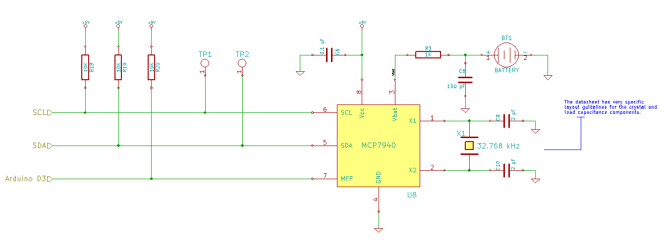
Schematic
Education Shield – MCP7940 RTCC Subsystem
Setup
For this module, you’ll need the following equipment:
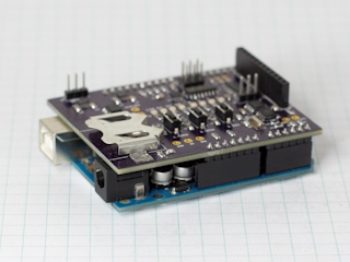
- I2C and SPI Education Shield or the MCP7940 Breakout Board
- Arduino UNO R3
1. Mate the Education Shield with your Arduino UNO R3. If you’re using the MCP7940 Breakout Board, connect 5V to 5V, GND to GND, SCL to Analog 5, SDA to Analog 4 and MFP to Digital3.
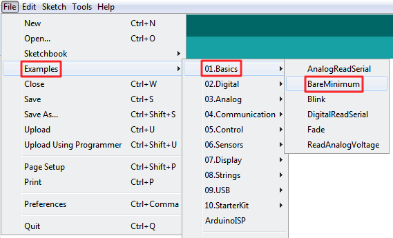
2. Connect your Arduino to your USB cable, and use the Arduino IDE to upload the “Bare Minimum” sketch from the Basics section of the Examples.
MCP7940 Tutorial: A Quick Rant
Before we get started on setting and retrieving anything time related, I want to clearly explain how to make the chip actually work. This is a common issue when dealing with ICs… you design your schematic, get a prototype board spun, write some basic test code and the blasted thing just… doesn’t… work. Invariably, there is some teeny little bit hidden away in the datasheet that is the “ON” bit or the “ENABLE” bit or “I/O” bit or something like that… essentially an on/off switch.
As an exercise, open up the MCP7940 datasheet, and try to find where it explains how to make the clock run. If you get frustrated, here’s the answer…
Determine how to turn on the MCP7940 functionality…
Hover to read answer
I have read through that datasheet, without exaggeration, at least a hundred times in preparation for writing these education modules, and to this day I have yet to see where that is clearly spelled out.
Anyway…
Binary-coded Decimal
Our date and time values are stored in Binary-Coded Decimal (BCD). Let’s examine the seconds register and see how we can convert values to and from BCD and regular decimal.
The seconds register is comprised of a set of three bits that make up the tens place of a decimal number and a set of four bits that make up the ones place of a decimal number. The most significant bit, the eighth bit of RTCSEC, has special powers which we’ll worry about below… for now, we’ll just label it as “x”. So, if you have the number 25, you would split it into 2 and 5, and then convert each into its equivalent binary value, and mash the two back together with the binary value for 2 on the left and the binary value for 5 on the right and spit that into the register.
|
1 2 3 4 |
25 2 = Bx010 5 = B0101 BCD 25 = Bx0100101 |
The BCD value can be a little confusing, because you can’t simply process it as is. BCD Bx0100101 = 25, while the regular binary value Bx0100101 = 37.
The conversion back from BCD to regular decimal is pretty much the converse of that process. The register map tells us how many bits are assigned to the tens and ones places, so we just split, convert and recombine again… just in the other direction.
|
1 2 3 4 |
Bx1010111 Bx101 = 5 B0111 = 7 BCD Bx1010111 = 57 |
Convert 38 seconds to BCD…
Hover to read answer
Convert BCD Bx0010110 seconds to decimal…
Hover to read answer
So now that we know how to convert to and from BCD mechanically, how do we do it programmatically? It turns out to be pretty easy, actually, when you use the “modulo” operator. Instead of using the “/” you use “%” and what it does is return the remainder from your division operation instead of the whole number. By using both, you can extract the tens place and the ones place pretty easily. Then just use a little bit shifting…
|
1 2 3 |
byte convertToBcd(byte byteDecimal) { return(byteDecimal / 10) << 4 | (byteDecimal % 10); } |
To convert from BCD back to Decimal is preeeeetty much the converse. Take the binary value, split it into two separate variables and shift the MSB byte over to the left, then multiply the MSB Byte times ten and add it to the LSB Byte. You could take this code and eliminate the extra variables entirely by squashing everything together into one command, but it would be impossible to understand.
|
1 2 3 4 5 6 7 |
byte convertFromBcd(byte byteBCD) { byte byteMSB = 0; byte byteLSB = 0; byteMSB = (byteBCD & B11110000) >> 4; byteLSB = (byteBCD & B00001111); return((byteMSB*10) + byteLSB); } |
This code is only sending bytes back and forth, so if you wanted to use it on larger values like integers, you’d have to change the variable types to accommodate more than 8 bits.
Now, you could choose to do this mathematically instead, rather than using bit shifting. The lower four bits are equal to their value multiplied by 1 and the upper four bits are equal to their value multiplied by 16. Why 16? Because the first value in the upper byte is B00010000 = 16, so multiplying them by 16 is the equivalent of shifting the bits over four places to the left.
So, in order to convert from Decimal To BCD…
\[\mathtt{\left[\frac{value}{10}\right ]\times16 + \left(val\%10\right)}\]
and to convert form BCD back into Decimal…
\[\mathtt{\left[\frac{value}{16}\right ]\times10 + \left(val\%16\right)}\]
The choice is yours for how you want to do your conversion.
MCP7940 Tutorial: Configuration Planning
We’re going to start very simply: setting the time and retrieving the time. We won’t worry about trimming the oscillator, setting alarms or any of that stuff yet.
Looking at the register map, we see that the top of the register addresses are all time and date related. That’s where we need to start concentrating our efforts. To make it a little easier to read, I’ve removed all the non-time related bits from the following register map.
| Address | Name | Bit7 | Bit6 | Bit5 | Bit4 | Bit3 | Bit2 | Bit1 | Bit0 |
|---|---|---|---|---|---|---|---|---|---|
| 0x00 | RTCSEC | ST | SECTEN2 | SECTEN1 | SECTEN0 | SECONE3 | SECONE2 | SECONE1 | SECONE0 |
| 0x01 | RTCMIN | MINTEN2 | MINTEN1 | MINTEN0 | MINONE3 | MINONE2 | MINONE1 | MINONE0 | |
| 0x02 | RTCHOUR | 12/24 | AM/PM | HRTEN0 | HRONE3 | HRONE2 | HRONE1 | HRONE0 | |
| 0x03 | RTCWKDAY | WKDAY2 | WKDAY1 | WKDAY0 | |||||
| 0x04 | RTCDATE | DATETEN1 | DATETEN0 | DATEONE3 | DATEONE2 | DATEONE1 | DATEONE0 | ||
| 0x05 | RTCMTH | LPYR | MTHTEN0 | MTHONE3 | MTHONE2 | MTHONE1 | MTHONE0 | ||
| 0x06 | RTCYEAR | YRTEN3 | YRTEN2 | YRTEN1 | YRTEN0 | YRONE3 | YRONE2 | YRONE1 | YRONE0 |
We have a few things in our favor when it comes to setting all those values. First, once we figure out how to set the values for one of these things, we’ll know how to set it for all of them. Second, the time and date registers read and write sequentially, just like the SRAM does, so we can start writing our seconds register and just flow into the next and the next, etc. Third, since we’re not really going to be going in and writing to these registers repeatedly, we can set the time and date bits first, and set everything else to zero, then go in and set any configuration bits afterwards before flipping the ST bit.
So what we’ll do, is start setting the seconds register by sending in our BCD value, then move down the register list in order, filling the appropriate values. Then we’ll set whatever configuration bits we need to, and after that, we’ll flip the ST bit to start the clock and then start printing out the time.
|
1 2 3 4 5 6 7 8 9 10 11 12 13 |
#include "I2C.h" const int MCP7940_I2C = 0x6F; // I2C Address for the RTC const int REG_RTCSEC = 0x00; // Register Address: Time Second const int REG_RTCMIN = 0x01; // Register Address: Time Minute const int REG_RTCHOUR = 0x02; // Register Address: Time Hour const int REG_RTCWKDAY = 0x03; // Register Address: Date Day of Week const int REG_RTCDATE = 0x04; // Register Address: Date Day const int REG_RTCMTH = 0x05; // Register Address: Date Month const int REG_RTCYEAR = 0x06; // Register Address: Date Year byte timeStamp[7]; // Byte array holding a full time stamp. |
As usual, we start the sketch with our declarations, defining constants for our I2C and register addresses. We’re also creating a byte array called “timeStamp” that will hold the full set of time and date values we read and write to the MCP7940. Since there are seven registers, we size the array with seven positions.
|
1 2 3 4 5 6 7 8 9 10 11 12 13 14 15 16 17 18 19 20 21 22 23 24 25 26 |
void setup() { Serial.begin (9600); I2c.begin (); // Initialize the I2C library I2c.pullup (0); // Disable the internal pullup resistors I2c.setSpeed (0); // Enable 100kHz I2C Bus Speed I2c.timeOut (250); // Set a 250ms timeout before the bus resets // These are the values that will be written to the MCP7940 timeStamp[0] = convertToBcd( 0); // SECONDS timeStamp[1] = convertToBcd( 07); // MINUTES timeStamp[2] = convertToBcd( 14); // HOURS timeStamp[3] = convertToBcd( 6); // DAY OF WEEK (arbitrary value 1 - 7) timeStamp[4] = convertToBcd( 27); // DAY timeStamp[5] = convertToBcd( 03); // MONTH timeStamp[6] = convertToBcd( 15); // YEAR // Write our time stamp to the time/date registers I2c.write(MCP7940_I2C, REG_RTCSEC, timeStamp, 7); // Initialize our chip with any further configuration data init_MCP7940(); } |
There is so much magic happening in that Setup function because of the I2C library, it’s amazing. At the top, all we do is start our Serial connection, no big deal, but then we set four parameters for our I2C is going to function. We start it, we turn off the internal pullup resistors, we set the speed to 100kHz and we specify a bus timeout of 250ms. It’s so nice to know that you’re setting it assertively, rather than just expecting some backend library to contain the configuration without you knowing.
After that, we load the timeStamp array with a series of values. You can obviously see what time I was writing this education module 🙂
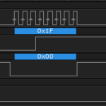
Then, in one command, we transfer all the data into the MCP7940 at once. BANG! Here’s what I2c.write(MCP7940_I2C, REG_RTCSEC, timeStamp, 6); looks like on the oscillocscope…
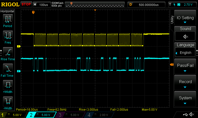
After we set the time, we call our chip initialization function that we’ll use to set some configuration parameters. Have a look at this…
|
1 2 3 4 5 6 7 8 9 10 11 12 13 14 15 16 17 18 19 |
void init_MCP7940() { byte registerValue = 0x00; // Holds the received register value byte twelveHour = 0x00; // 0 = 24 Hour Clock Mode / 1 = 12 Hour Clock Mode byte startClock = 0x01; // 0 = Start Oscillator / 1 = Stop Oscillator // Turn on/off: 12 hour vs. 24 hour clock I2c.read (MCP7940_I2C, REG_RTCHOUR, 1); registerValue = I2c.receive(); if (twelveHour == 0x00) I2c.write (MCP7940_I2C, REG_RTCHOUR, bitClear (registerValue, 6)); if (twelveHour == 0x01) I2c.write (MCP7940_I2C, REG_RTCHOUR, bitSet (registerValue, 6)); // Turn on/off: Oscillator (starts the clock) I2c.read (MCP7940_I2C, REG_RTCSEC, 1); registerValue = I2c.receive(); if (startClock == 0x00) I2c.write (MCP7940_I2C, REG_RTCSEC, bitClear (registerValue, 7)); if (startClock == 0x01) I2c.write (MCP7940_I2C, REG_RTCSEC, bitSet (registerValue, 7)); } |
The only two items we have in there, for now, are enabling or disabling the 12 hour clock mode, and turning the oscillator on or off. Now, we could have placed the values directly into the I2C functions, but I think this makes it more clear which settings you’re using at the expense of a little bit of memory space in the form of two bytes of variables, and a little processing time.
You set the parameter you want at the top as a single bit. Now, because the configurations appear inside the date and time registers, we have to retrieve the current value, so we can send it back, with the configuration bit changed as we desire. A quick check of the bit we’re trying to pass occurs with the if statement: 0x00 = bitClear, 0x01 = bitSet.
When we start adding more configurations for oscillator trimming, battery enable, etc, we can set all of that in here using the same pattern, and it will make it much easier to keep track of when you return to the code after a few months.
MCP7940 Tutorial: Retrieving and Displaying the Time
Now, after all that I wish I could give the big reveal on how we’re going to grab the time value, but really, the I2C library makes it really easy at this point.
|
1 2 3 4 5 6 7 8 9 10 11 12 13 14 15 16 17 |
void loop() { I2c.read(MCP7940_I2C, REG_RTCSEC, 7, timeStamp); Serial.print ("Current Time: "); Serial.print (convertFromBcd(timeStamp[2] & 0x3F)); Serial.print (":"); if (convertFromBcd(timeStamp[1] & 0x7F) / 10 == 0) Serial.print ("0"); Serial.print (convertFromBcd(timeStamp[1] & 0x7F)); Serial.print (":"); if (convertFromBcd(timeStamp[0] & 0x7F) / 10 == 0) Serial.print ("0"); Serial.println (convertFromBcd(timeStamp[0] & 0x7F)); delay(1000); } |
The I2C command retrieves seven bytes of data, starting at the the location REG_RTCSEC. Because the MCP7940 is able to read from the registers sequentially, it just moves from one to the next to the next. Our function handily loads all of those values directly into the timeStamp array for us. We’re done using it to set the time, so we may as well use the same variable to hold the current time now.
Then, we send the values to the Serial monitor. It’s not entirely easy to do that though. Remember, our values have two that need to be changed before we can recognize them as human readable numbers…
- They contain configuration bits that need to be masked off.
- They are in BCD format.
In order to eliminate the configuration information, we AND the raw data in the timeStamp array with the appropriate mask.
|
1 2 3 4 5 6 7 8 9 10 11 12 13 14 15 16 17 |
Raw Hour Value = "H" BxxHHHHHH & B00111111 ----------- B000HHHHH Raw Minute Value = "M" BxMMMMMMM & B01111111 ----------- B0MMMMMMM Second Value = "S" BxSSSSSSS & B01111111 ----------- B0SSSSSSS |
After we mask off the unwanted bits, we can take the remaining data and send it to convertFromBcd and send it straight to the Serial monitor. The if statements check to see if the value returned is less than ten, and if it is, it appends the field with a “0”, since we’re used to seeing minute and second values represented as two digits.
Here’s the full code all assembled for you to refer to…
|
1 2 3 4 5 6 7 8 9 10 11 12 13 14 15 16 17 18 19 20 21 22 23 24 25 26 27 28 29 30 31 32 33 34 35 36 37 38 39 40 41 42 43 44 45 46 47 48 49 50 51 52 53 54 55 56 57 58 59 60 61 62 63 64 65 66 67 68 69 70 71 72 73 74 75 76 77 78 79 80 81 82 83 84 85 86 87 88 89 90 91 92 93 94 95 96 97 98 99 100 101 102 103 104 105 106 107 108 |
/* A sketch to set and retrieve the time from the MCP7940 RTC on the Rheingold Heavy I2C and SPI Education Shield. Website: https://rheingoldheavy.com/mcp7940-tutorial-02-setting-and-getting-time Datasheet: http://ww1.microchip.com/downloads/en/DeviceDoc/20005010F.pdf */ #include "I2C.h" const int MCP7940_I2C = 0x6F; // I2C Address for the RTC const int REG_RTCSEC = 0x00; // Register Address: Time Second const int REG_RTCMIN = 0x01; // Register Address: Time Minute const int REG_RTCHOUR = 0x02; // Register Address: Time Hour const int REG_RTCWKDAY = 0x03; // Register Address: Date Day of Week const int REG_RTCDATE = 0x04; // Register Address: Date Day const int REG_RTCMTH = 0x05; // Register Address: Date Month const int REG_RTCYEAR = 0x06; // Register Address: Date Year byte timeStamp[7]; // Byte array holding a full time stamp. // Array position is the same as the register address. void setup() { Serial.begin (9600); I2c.begin (); // Initialize the I2C library I2c.pullup (0); // Disable the internal pullup resistors I2c.setSpeed (0); // Enable 100kHz I2C Bus Speed I2c.timeOut (250); // Set a 250ms timeout before the bus resets // These are the values that will be written to the MCP7940 timeStamp[0] = convertToBcd( 0); // SECONDS timeStamp[1] = convertToBcd( 07); // MINUTES timeStamp[2] = convertToBcd( 14); // HOURS timeStamp[3] = convertToBcd( 6); // DAY OF WEEK (arbitrary value 1 - 7) timeStamp[4] = convertToBcd( 27); // DAY timeStamp[5] = convertToBcd( 03); // MONTH timeStamp[6] = convertToBcd( 15); // YEAR // Write our time stamp to the time/date registers I2c.write(MCP7940_I2C, REG_RTCSEC, timeStamp, 7); // Initialize our chip with any further configuration data init_MCP7940(); } void loop() { I2c.read(MCP7940_I2C, REG_RTCSEC, 7, timeStamp); Serial.print ("Current Time: "); Serial.print (convertFromBcd(timeStamp[2] & 0x3F)); Serial.print (":"); if (convertFromBcd(timeStamp[1] & 0x7F) / 10 == 0) Serial.print ("0"); Serial.print (convertFromBcd(timeStamp[1] & 0x7F)); Serial.print (":"); if (convertFromBcd(timeStamp[0] & 0x7F) / 10 == 0) Serial.print ("0"); Serial.println (convertFromBcd(timeStamp[0] & 0x7F)); delay(1000); } void init_MCP7940() { byte registerValue = 0x00; // Holds the received register value byte twelveHour = 0x00; // 0 = 24 Hour Clock Mode / 1 = 12 Hour Clock Mode byte startClock = 0x01; // 0 = Start Oscillator / 1 = Stop Oscillator // Turn on/off: 12 hour vs. 24 hour clock I2c.read (MCP7940_I2C, REG_RTCHOUR, 1); registerValue = I2c.receive(); if (twelveHour == 0x00) I2c.write (MCP7940_I2C, REG_RTCHOUR, bitClear (registerValue, 6)); if (twelveHour == 0x01) I2c.write (MCP7940_I2C, REG_RTCHOUR, bitSet (registerValue, 6)); // Turn on/off: Oscillator (starts the clock) I2c.read (MCP7940_I2C, REG_RTCSEC, 1); registerValue = I2c.receive(); if (startClock == 0x00) I2c.write (MCP7940_I2C, REG_RTCSEC, bitClear (registerValue, 7)); if (startClock == 0x01) I2c.write (MCP7940_I2C, REG_RTCSEC, bitSet (registerValue, 7)); } byte convertToBcd(byte byteDecimal) { return (byteDecimal / 10) << 4 | (byteDecimal % 10); } byte convertFromBcd(byte byteBCD) { byte byteMSB = 0; byte byteLSB = 0; byteMSB = (byteBCD & B11110000) >> 4; byteLSB = (byteBCD & B00001111); return ((byteMSB * 10) + byteLSB); } |
