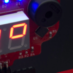
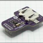
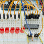
One of my design requirements for the I2C and SPI Education Shield was to make it expandable, and the first board I’ve developed to work with it, is the Education Shield Display Board – I wanted to give an Education Shield user the ability to direct the outputs of their work to a variety of different feedback mechanisms. To reach that goal, I designed the Display Board with a four digit seven segment display with both clock and decimal digit mode, two rows of 8 Red-Green bi-color LEDs in a bar graph configuration and a piezo speaker. All of that is controlled using I2C, one PWM pin and one digital output from your Arduino. The board itself will plug right into the end of the Education Shield so it’s easy to connect and get running right away!
Some of the ways you can use the board with the Education Shield are…
- Digital alarm clock
- Binary clock display
- Play tones stored in SRAM
- Direct display of numeric ADC values
- Combination of both ADC value as well as ADC channel being measured.
- Audio/Visual alarm on interrupt
- Numeric temperature display
- Bar graph display of ADC level
- Bar graph display of temperature value
- Extensive visualization of bitwise operations
Originally, I was only going to place a seven segment clock display on it. Then ambition got the better of me and I selected a four digit display with both clock and decimal LEDs. Of course, if you’re going to have a clock, you have to let it play an alarm, which meant adding a speaker. Then I thought it would be cool if there was an analog visualization as opposed to reading digits, so I put a row of LEDs on it. Well, if you were going to put a row of LEDs on there, why not put bi-color LEDs so you can do something like a threshold meter. Finally, you start doing your final check on the schematic and PCB layout and realize that there are enough multiplex control pins remaining to run a second row of LEDs, so why not put two rows of LEDs on there?
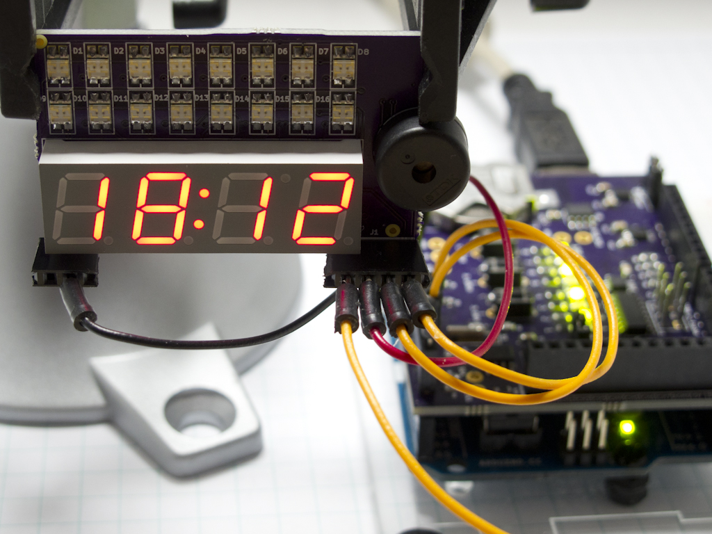
So, what I thought would take a couple of hours on a Saturday to put together, turned into a tight little board with 99 connections and 49 vias that took 30 hours to engineer.
Here are some display tests, showing the different configurations that can be achieved. The crappy contrast of the images is entirely a result of the difficulty I had in taking photographs of incredibly bright LEDs, not the result of low contrast displays.
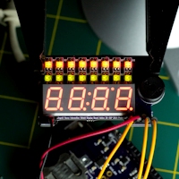 1. Test Pattern
The display board driver has a built in test routine that brings all active circuits high. The bottom row of the bar graph only displays the green LEDs because a SPDT switch IC adds a layer of multiplexing, enabling either the lower row of red LEDs, or the time colon LEDs. The switch is governed by user code, not the driver IC.
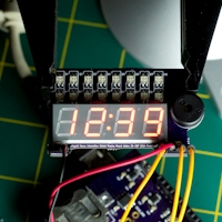 2. Clock Display
In this instance, the bar graph is disabled, and the seven segment display is showing the time generated by the Education Shield Real Time Clock. The SPDT IC is configured to enable the colon between the hours and minutes display, but could be multiplexed to allow the full bar graph to work with the time as well.
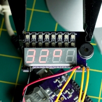 3. Temperature
A temperature value read from the Education Shield I2C temperature sensor is showing on the display. The first two digits are shown as full numbers while the third digit is customized to display as a degree symbol. The fourth digit and the bar graph are disabled.
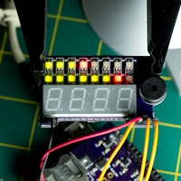 4. Bar Graphs
The two rows of red/green LEDs at the top are being used as a pair of bar graphs, while the seven segment display is disabled entirely. The individual LEDs are addressed as a single byte, and each of the color rows are addressed by their own register, so it’s very easy to set the farthest position of your graph to the opposing color.
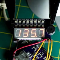 5. Decimal Values
Floating Point values can be displayed by adding a decimal place. Decimal points are available to the immediate right of each of the digits and are enabled by writing the MSB for that digit’s register high. They are controlled independently of the “time colon” separator.
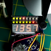 6. Combined Display
In this case, the bar graphs are displaying readings from two separate ADCs, while the four digit display presents a decimal value simultaneously.
Update 20-SEP: Here are the preliminary renders from OSHPark. The location of the piezo speaker element on the right of the board will actually have an edge cut that is a half circle around the physical footprint of the speaker, not a rectangle.
[masterslider id=22]
Update 21-SEP: Thought about it overnight and realized I needed to provide a relief in the board outline along the bottom for the ADC connector I put on the Education Shield. I also forgot to put some silkscreen goodies on it. So a couple of sweet curves later and some judicious rerouting, I think I’m ready to get the board spun. Here are the new renders…
[masterslider id=23]
