Moving bits around with buttons is the introduction to serial communications control, now let’s adapt the techniques we performed manually to code in the Arduino IDE.
Objectives
- Understand the term bit banging.
- Replicate the button functionality using Arduino code.
Background
Fundamentals of Serial Communications
Electrical View of the Shift Register
Decimal, Binary and Hexadecimal Number Systems
Decimal and Binary Number Conversion
Binary and Hexadecimal Number Conversion
Schematic
Education Shield – Shift Register Subsystem
Setup
For this module, you’ll need the following equipment:
- Education Shield or the Manual Serial Communications Trainer
- Arduino UNO R3
1. Place jumpers on each of the 74HC595 Enable block pins along the edge of the Education Shield. This will enable microcontroller interaction with the shift register.
2. Mate the Education Shield with your Arduino UNO R3.
3. Finally, connect your Arduino to your USB cable, and upload this little sketch to drive the OE pin low.
|
1 2 3 4 5 6 7 |
void setup() { int oePin = 5; pinMode (oePin, OUTPUT); digitalWrite (oePin, LOW); } void loop() {} |
Alternatively, you can use the Manual Serial Communications Trainer instead. Connect 5V and CLR to 5V, GND and OE to GND, DATA to D8, LATCH to D7, and CLOCK to D6. No code is required.
Brute Force Control
While pressing buttons to control the flow of bits helps to understand the mechanics of serial communications, it isn’t very fast. We need to begin controlling our devices using code executed at microprocessor speed instead, to speed things up. The buttons on your Education Shield provide very clearly defined high / low signals, just like the digital pins on the Arduino do. That makes it very easy to map their function directly onto the pins with C code.
Placing jumpers on the 74HC595 Enable pin headers connects your Arduino directly to the shift register in the following pattern…
- Clock = Digital 6
- Latch = Digital 7
- Data = Digital 8
- OE = Digital 5
… and with those jumpers in place, a very simple sketch can be written to perform exactly the same activity that you executed using the buttons alone. (If the LEDs on the Education Shield are not all lit, briefly unplug and replug the USB cable to completely reset the system.)
|
1 2 3 4 5 6 7 8 9 10 11 12 13 14 15 16 17 18 19 20 21 22 23 24 25 26 27 28 29 30 31 32 33 34 35 36 37 38 39 40 41 42 43 44 45 46 47 48 |
/* Basic Sketch To Control a 74HC595. Brute Force Method 01 https://rheingoldheavy.com/bit-banging-the-74hc595 This sketch is designed to work with the Rheingold Heavy Education Shield. */ // Set the pin connections from the shift register int clockPin = 6; int latchPin = 7; int dataPin = 8; int oePin = 5; // We use the doOnce variable as a simple way to keep the main loop from reexecuting the code. int doOnce = 1; void setup() { // The pins will be generating levels, not sensing levels, so put them in OUTPUT mode. pinMode(latchPin, OUTPUT); pinMode(dataPin, OUTPUT); pinMode(clockPin, OUTPUT); pinMode(oePin, OUTPUT); // Preset the pin states so that there's no guessing where anything is. digitalWrite (clockPin, LOW); digitalWrite (latchPin, HIGH); digitalWrite (dataPin, LOW); digitalWrite (oePin, LOW); } void loop() { // This IF statement will only execute once, because the doOnce variable is set to 0 at the end of execution if (doOnce == 1) { digitalWrite (dataPin, LOW); // Ensure the data pin is low digitalWrite (clockPin, HIGH); // Set the clock high. Since the data pins is low, this will clock in a zero digitalWrite (clockPin, LOW); // Bring the clock low again digitalWrite (latchPin, LOW); // Bring the latch low so it can be brought high again. digitalWrite (latchPin, HIGH); // Bring the latch high to commit the bit to the shift register outputs doOnce = 0; // Set doOnce to zero so that the IF statement doesn't process again } } |
After uploading the sketch to your Arduino, the right most LED should have gone out, just as it did when you pressed the clock button and then the latch button. The code is designed to only fire once, but the serial monitor in the Arduino IDE functions as a system reset, so if you open and close and open and close the serial monitor repeatedly, you’ll see the LEDs wink out of existence one at a time.
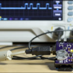
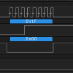
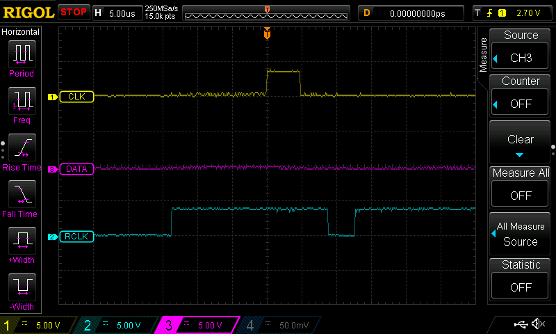
Here is what it looks like on an oscilloscope. You can see the single pulse of the data pin and the single drop of the latch pin. The latch pin is goes high at the far left of the trace when the pin is set high in the setup.
The code is fairly simple, but I’ll break it down step by step.
|
1 2 3 |
int clockPin = 6; int latchPin = 7; int dataPin = 8; |
Here we assign a series of variables to hold the value of our digital pins in easy to read formats. The clock pin on the 74HC595, called SRCLK in the datasheet, is Digital 6. The latch, RCLK, is Digital 7 and data, SER, is Digital 8. These connections are hard wired in the copper traces of the PCB, but are normally separated unless connected by the 74HC595 Enable jumpers.
|
1 2 3 |
pinMode(latchPin, OUTPUT); pinMode(dataPin, OUTPUT); pinMode(clockPin, OUTPUT); |
Our clock, data and latch pins are all going to be setting values of either 0V or 5V, so we set them up as outputs in the void setup() .
|
1 2 3 |
digitalWrite (clockPin, LOW); digitalWrite (latchPin, HIGH); digitalWrite (dataPin, LOW); |
Since these pins are going to be used to send data, we need to make sure that they are in an expected safe state so that nothing happens when we first get things going. By placing the clock and data low, there’s no way that any bits will be sent to the 74HC595, and since the latch is high, we can’t commit any changes any way, without cycling that pins state.
|
1 2 3 4 5 |
digitalWrite (dataPin, LOW); // Ensure the data pin is low digitalWrite (clockPin, HIGH); // Set the clock high. Since the data pins is low, this will clock in a zero digitalWrite (clockPin, LOW); // Bring the clock low again digitalWrite (latchPin, LOW); // Bring the latch low so it can be brought high again. digitalWrite (latchPin, HIGH); // Bring the latch high to commit the bit to the shift register outputs |
This is where the magic, such as it is, happens. This sketch is designed to clock in a single zero, so first we double check that the data pin is set low. Then the clock pin is brought high, and on the rising edge of that signal, the value of the data pin is sampled, resulting in a zero being clocked in. The clock pin is brought low, signifying the end of a bit of data. Latch is brought low, essentially so that it can be brought high again, and on the rising edge of the latch signal, that single zero is brought to the outputs. All of this is done inside a simple IF statement that only runs when the variable doOnce is equal to 1, which it can only be the first time the IF statement is executed, because it’s changed right at the end of all those digitalWrites, by design.
What we’ve just done is bit bang the Arduino. Bit banging means to manually control the process of sending or receiving bits through the direct manipulation of pin states in software. Really, the interface and timing of a 74HC595 is so rudimentary, that there’s no real reason for advanced coding or special pin types to handle it, so generally, bit banging is the way to manipulate the component. I2C and SPI both have specialized pins on many microcontrollers that are setup in the silicon to function a certain way, which makes it easier for the person writing code to work with them. If you were to bit bang them instead, you’d be specifically controlling the high and low states of the entire process, which becomes quite difficult when you’re not setting pins at a microsecond rate but in nanoseconds and clock cycles.
Here is some replacement code that will turn the LEDs back on, one at a time, instead of turning them off.
|
1 2 3 4 5 6 |
digitalWrite (dataPin, HIGH); digitalWrite (clockPin, HIGH); digitalWrite (clockPin, LOW); digitalWrite (dataPin, LOW); digitalWrite (latchPin, LOW); digitalWrite (latchPin, HIGH); |
Replace the sequence of digital writes inside the IF loop with those commands, and each time you open and close the serial monitor, you’ll light an LED instead of turning one off. You should be able to see the two changes that were made to the code to allow that to happen.
