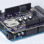
In Part 5, we brought the voltage comparator to a tentative conclusion (still need those LDO output caps), now we’re going to use up that last op-amp in the LMV358 package to control an LED on pin 13.
Build An Arduino UNO R3 from Scratch Table of Contents
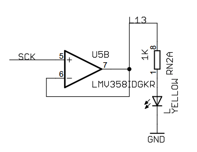
The Official Circuit and the How of it
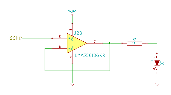
Chances are, this was the first thing you did when you got your first Arduino: load up Blink.ino from the Examples and set yourself onto a life long love of voltage, amperage and ohms, as that yellow surface mount LED blinked away one second on, one second off. This is the circuit that did that.
Your first reaction at seeing that is, “well that’s WAY overbuilt”, but it isn’t, at least as far as I can tell. Give me a moment to engage the uninformed speculation engine.
There had to be something that could be done, right out of the box, as soon as you got the board plugged into your computer. Something super simple, super easy, that you could use to validate the whole tool chain from IDE to USB Cable to Board, and the Hello World! of hardware is the blinking LED. But where to put it? Well, for this purpose, any pin is just as good as any other, so may as well stick it in a corner, and that turns out to be near Arduino Digital 13 (actual 328P pin 19). Now the second thing you probably did, was stick your own LED and resistor in a breadboard and blink THAT. So you can see we have the resistor and the LED, what’s with the op-amp?
Well, the op-amp is connected in this instance, as a buffer. In the voltage management section, remember how the output was entirely isolated from the inputs? In this case, the output is directly fed back into the inverting input. As before, the output will do it’s absolute best equalize the two inputs. When the non-inverting input changes in value to any voltage other than the inverting input in either direction, the output will compensate to make the inverting output be equal, which results in the output being an exact mirror of the non-inverting input — when everything is in equilibrium, both inputs and the outputs are exactly at the same voltage: non-inverting input is mirrored on the output, a buffer.
You may say, “well I didn’t need to buffer my signal when I connected my resistor and LED on the other pin”, and that is true, because you have chosen that pin, in that case, to light an LED, and take all the current it needs to do it. However, this Pin 13 LED, is going to be there for the life of the board, so it’s important that it’s presence doesn’t affect anything else that the pin might need to do, like act as the SCK pin for SPI. You want the full current capability of the pin to be available for any other task it can possibly perform, and the op-amp does that. How?
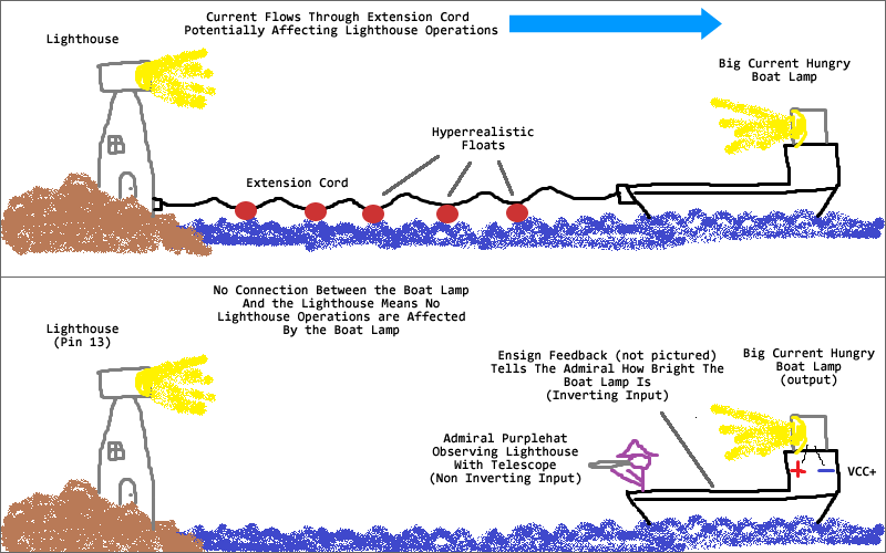
The inputs of an op-amp draw no current at all (ideal op-amp disclaimer, blah, blah, blah). You can think of the Pin 13 LED as being a giant current hungry (ok, not terribly hungry, on the order of 10mA or so) lamp on a ship at sea. If you ran a massive extension cord with floats and waterproof connectors from the lighthouse out to the boat, you could power that light from the shore — when the lighthouse turns on, the boat lamp turns on — that’s the equivalent of connecting your resistor and LED directly to the pin. Using the op-amp, however, is like having the captain of the boat looking at the shore with binoculars to see when the lighthouse flips on… as soon as the lighthouse goes on, he flips a local switch to power up the giant current hungry lamp. In doing so, he accepted an input from the shore, but sourced the current to the lamp in a way that didn’t affect any systems on shore at all.
I know, worst analogy ever.
So, when Pin 13 is energized by a digitalWrite command, the non-inverting input is raised to 5V, which drives the output to 5V, but sources the voltage and current from the op-amps VCC+ pin, which doesn’t cause any effect back at pin 13.
Limitations Of Pin 13 LED
When you connect an LED directly (through a resistor) to a PWM pin and start pulsing it, you see the pulses manifest as the LED turning on and off. As you increase the PWM value, you shorten the pulse widths, and they start to melt into one, making it seem as though the LED is on continuously. It turns out, that doesn’t work with Pin 13. As you decrease the pulse width, the op-amp starts to lag in it’s ability to keep up with the rapid changes of Pin 13. The slew rate of the op-amp is 1V/uS, meaning it takes five full microseconds to do a full shift from 0V to 5V. When your pulse width is less than that, it starts getting trapped partially into a rising state when the signal on the non-inverting opamp starts falling again. It can’t keep up. The result is that the LED actually starts to get dimmer and dimmer, until you reach a frequency at which the op-amp basically gives up.
Here’s a goofy little sketch you can use to test this (for more information on why PORT commands are used here instead of digitalWrite, read the post on Sampling Audio Signal Frequencies With The MCP3008 ADC)
|
1 2 3 4 5 6 7 8 9 10 11 12 13 14 15 16 17 18 19 20 21 22 23 24 25 26 27 28 29 30 31 32 33 34 35 36 37 |
/* Hammer Pin 13 This little sketch will execute a port command against Arduino Pin 13. Pin 13 is actually ATMEGA328P Pin 19, PORTB 5. As a way of adjusting the pulse length, the code below just repeatedly writes the pin high then repeatedly writes the pin low, based on the value of portReps. Overwriting the port value with the same value doesn't affect the output, but takes up clock cycles, resulting in a crappy simulation of PWM on a non-PWM pin. */ void setup() { // Let's make Pin 13 an output. pinMode(13, OUTPUT); } void loop() { // This is how many times both the TURN THE PIN ON and TURN THE PIN OFF commands are executed sequentially long portReps = 200000; // Execute the port B command to bring Arduino Pin 13 high a bunch of times in a row for (long i = 0; i < portReps; i++) { PORTB = PORTB | 0x20; // Writes PORTB5 low } // Execute the port B command to bring Arduino Pin 13 low a bunch of times in a row for (long i = 0; i < portReps; i++) { PORTB = PORTB & 0xDF; // Writes PORTB5 low } } |
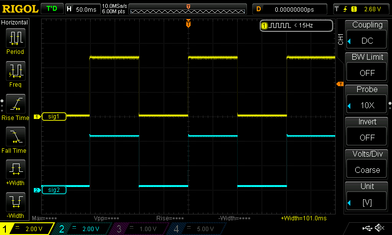
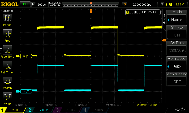
With the default portReps value of 200000, you create a PWM signal that’s visible on the pin 13 LED. It’s equivalent to writing a sketch that turns the LED on then turns the LED off with 100ms delays in between. Here’s what it looks like on the oscilloscope. The yellow trace on top is the signal at pin 13, the blue trace on the bottom is the output of the op-amp.
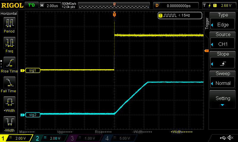
When we zoom in, the slew rate is plainly visible. At 2uS per division, you can see that the yellow trace just prangs straight up to 5V, but there’s a nearly linear ramp on the blue trace, taking just over 4uS (two divisions+) to match the output.
Now let’s reduce the size of the pulse width, by decreasing the value of portReps. At 2000 repetitions of on then 2000 repetitions of off, we drop the width by two orders of magnitude, to 1ms (frequency is about 440Hz… hey, you could tune a guitar with that!). No problem, we’re still good. Note that the scope is now at 500uS per division.
Let’s drop it again, this time to 200. The slew rate is obviously a large portion of the signal time, biting into the on and off portions of the yellow trace at the edges.
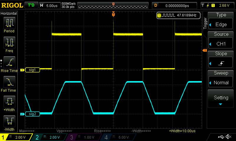
At 20 repetitions, our pulse width is down to 10uS, so we’re now taking up half the length of the pulse just to match and then half the length of the off time to drop back down. It’s about to get really funky…
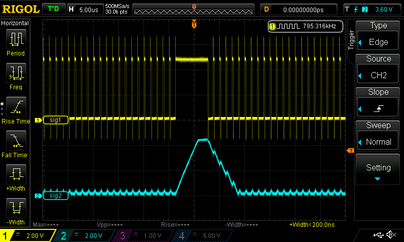
Here it is at 2 repetitions. The LED is essentially totally out now at 795kHz. The op-amp is trying over and over and over and over to catch up with the pin 13 signal, but just can’t, execept for every so often, when everything lines up and it has this glorious moment to stretch (like me at the end of an cross country flight), but gets immediately dragged back down. This seems to happen repeatedly every 4mS. Ignore the seemingly large positive pulse on the yellow trace, that’s an artifact of triggering the scope on the op amp signal instead of the PWM signal. The signal is constantly rising on a 5V period of the Pin 13 trace, making it all blend together.
This is why you never see the LED light up when you’re doing SPI stuff. It can only handle a really slowish on/off pulse.
Sourcing the Pin 13 LED Parts
Well, the funny thing is, we’ve pretty much sourced all the parts already. The op-amp is just the second unit inside the Texas Instruments LMV358IDGKR dual op-amp package, with the comparator one. The LED will be exactly the same LED type we used for the Power On LED in the voltage regulator subsystem schematic, with the same current limiting resistor. Really, it’s why and how it’s used that’s novel here, not so much the parts themselves.
Here’s the Pin 13 LED schematic in KiCad…
Here’s the Pin 13 LED BOM: Arduino Uno R3 From Scratch Pin13 LED Subsystem.csv
In part 7, we’ll start in on the USB connector and a whole bunch of static discharge protection.
