Objectives
- Select the values that should be modified in the configuration register.
- Understand how to deal with the pointer register.
- Write a setup function to contain any configuration parameters if necessary.
- Understand how the temperature value is returned and how to use a float variable.
- Initiate a temperature measurement and read the value to the serial monitor.
Background
AT30TS750A Functionality Overview
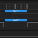
I2C Signaling
How To Read A Datasheet
Atmel AT30TS750A Datasheet
Arduino Reference on Float Variables
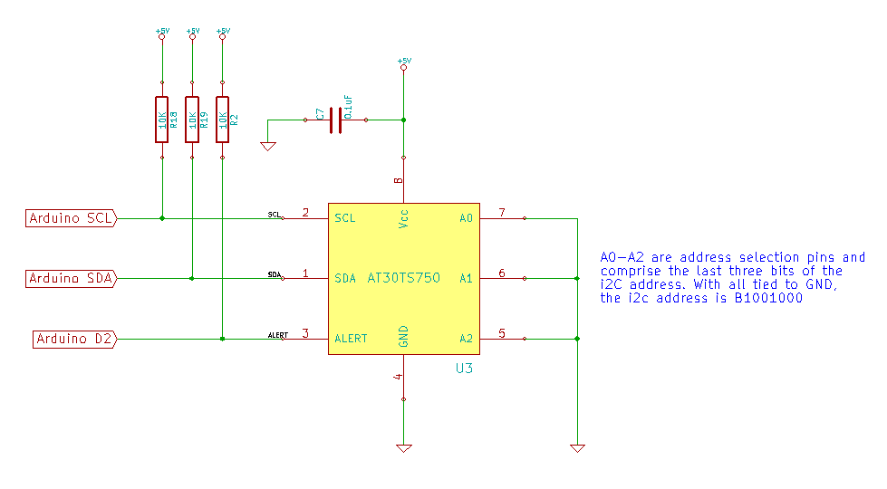
Schematic
Education Shield – AT30TS750A Temperature Sensor Subsystem
Setup
For this module, you’ll need the following equipment:
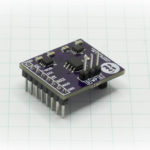
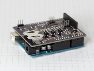
- I2C and SPI Education Shield or the AT30TS750A Breakout Board
- Arduino UNO R3
1. Mate the Education Shield with your Arduino UNO R3. If you’re using the AT30TS750A Breakout Board, check the labels by the pins and connect 5V to 5V, GND to GND, SC to Analog 5, SD to Analog 4 and AL to Digital2.
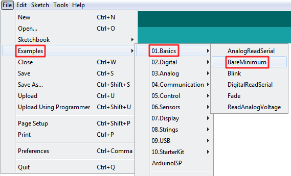
2. Connect your Arduino to your USB cable, and use the Arduino IDE to upload the “Bare Minimum” sketch from the Basics section of the Examples.
AT30TS750A Tutorial: Configuration Planning
The goal of this module will be to successfully retrieve a temperature measurement from the AT30TS750A. However, before we can do that, we need to examine the configuration and see if there’s anything that we should specify first. We’ll just ignore the Nonvolatile Registers (NVRs) for the time being. To refresh your memory, here is the configuration register from the datasheet…
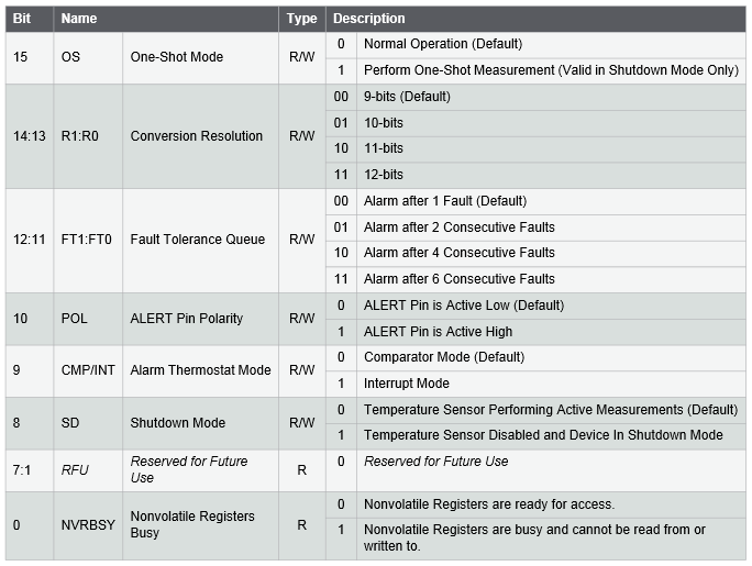
Looking at that, we can begin to make some decisions on how we want to test our chip. From my standpoint, I always want to test the single most basic functionality I can, that way I can verify that the circuit board layout is correct and I haven’t screwed anything up, except possibly for my code, which is why I keep that first part simple. So running from that standpoint, I would say that we can safely ignore dealing with Shutdown Mode, Thermostate Mode, worrying about Alert polarity, fault tolerance queues and one shot mode. In fact, the only thing I want to deal with is the conversion resolution. I want to test my chip at the default 9-bit reading and at 12-bits, to see what the returned difference is.
So, it looks like the only thing we want to change is the resolution and for our 9-bit test, that’s already the default, and for the 12-bit test, we need to change the 13:14 bits in the configuration to 11, without modifying any of the other values.
AT30TS750A Configuration Setting
When you look at the default values for all of the various configuration register addresses, you see that everything’s set to 0, especially since we haven’t messed around with the NVRs yet. That will make it very easy to change the resolution configuration, by merely sending the value 0x60 (B01100000). If you’re wondering why we’re only sending 8 bits when the configuration register is 16 bits wide, the first 8 bits are all read only, so even if we tried to send them data, it would just be ignored.
So, we’ll create a blank setup function to allow us to easily modify the measurement resolution. To do that, we merely need to tell the Arduino to do all the steps associated with an I2C Master Write command: Start Condition, I2C Slave Address, WRITE flag, Data and Stop Condition. From the library, we know that to achieve that, we use the commands Wire.beginTransmission(intAddress), Wire.write(data) and Wire.endTransmission().
The I2C address is determined by the pattern B1001AAA, where the three A’s correspond to the value of the three address pins, low or high. When I designed the Education Shield, I intentionally grounded the three address pins, so according to the datasheet then, the I2C address is 0x48 B1001000. Remember, the Wire.beginTransmission function will take care of shifting those bits over and adding the WRITE flag to the end of it.
|
1 |
Wire.beginTransmission(0x48); |
Now we need to write our data to the chip. We’ll leave it at 0 for now, but we can switch it to 0x60 to bump up the resolution…
|
1 |
Wire.write(0x00); |
And then we call the end function which makes the I2C do it’s thing…
|
1 |
Wire.endTransmission(); |
Now, you might think that you’re done, but not quite. We still need to tell the chip where to put the data. That’s where the pointer register comes in. Instead of just writing the byte of data to the chip, you first write the internal register address and then the data. The register map on page 14 says that the address of the configuration register is 0x01. So let’s add that to our list of commands, right before we write our configuration data…
|
1 2 3 4 |
Wire.beginTransmission (0x48); //Select the AT30TS750 for writing Wire.write (0x01); //Select the configuration register Wire.write (0x00); //0x00 = 9bit resolution, 0x60 = 12bit resolution Wire.endTransmission (); |
We also want this to be a function we can call from setup, so let’s call it init_AT30TS750A() …
|
1 2 3 4 5 6 |
void init_AT30TS750A() { Wire.beginTransmission (0x48); //Select the AT30TS750 for writing Wire.write (0x01); //Select the configuration register Wire.write (0x00); //0x00 = 9bit resolution, 0x60 = 12bit resolution Wire.endTransmission (); } |
Later we’ll capture the actual status returned by that last function, but we’re keeping it simple for now. It’s important to note that the pointer register handles a read vs. a write operation differently. Before you can perform a write operation, you must write the address where the data is going to go, to the pointer register. If you perform a read operation, you can continue to read from the same location over and over without resetting the pointer.
Taking the Temperature
Getting the temperature isn’t all that terribly different from how we set the configuration, but there is an added twist. When you set the pointer register on the chip, it remains set to that for every subsequent R/W instance, unless you change it. If we just issued a Wire.requestFrom command right now, we’d get back our configuration register values… which is cool, but not what we’re after. So we have to rewrite the pointer register to the temperature address first, then grab our temperature data. Since we’re going to stick with the 9-bits of data, we’ll need to grab two bytes back.
|
1 2 3 4 |
Wire.beginTransmission (0x48); //Select the AT30TS750 for writing Wire.write (0x00); //Select the temperature register Wire.endTransmission (); Wire.requestFrom (0x48, 2); //Retrieve two bytes of data |
At this point, we’ve pulled the data back into the internal I2C registers of the Arduino, but we need some place to work with them. So we’ll create two variables tempMSByte and tempLSByte to hold the most significant byte and least significant byte of our temperature reading. All data on I2C is sent MSB first, so we would expect, with a 9-bit value, that the last 7 bits of tempLSByte to be zero. It always helps if you have some idea of what the data should look like before you get it sent back.
|
1 2 3 4 5 6 |
Wire.beginTransmission (0x48); //Select the AT30TS750 for writing Wire.write (0x00); //Select the temperature register Wire.endTransmission (); Wire.requestFrom (0x48, 2); //Retrieve two bytes of data tempMSByte = Wire.read(); tempLSByte = Wire.read(); |
Assuming the code works and I designed the circuit correctly, we now have two bytes of a single dataset, and it would really be helpful if we combined them. Let’s think this through though, because this isn’t just a matter of bit shifting. We’re grabbing data that could potentially involve a decimal place, and will definitely involve a decimal place when we perform a conversion on it because the formula to convert from Celsius to Fahrenheit is…
\[(tempCelsius \times 1.8) + 32\]
That means we can’t use an integer to hold the value. If we were using the 8-bit Celsius value only, it wouldn’t matter, but we want to be able to accommodate the 12-bit resolution, so we’ll need to use a float. We also need to understand what the data looks like that is returned to us, and Atmel provided a handy example chart in the datasheet.
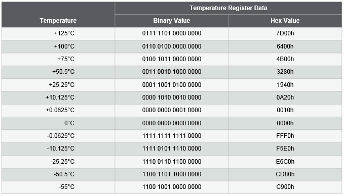
What you’ll notice, is that any temperature value that results in a whole number, only has data in the tempMSByte variable, and any decimal value we receive, will be returned in the tempLSByte variable. The greater the resolution, the more data we get back in the decimal portions of our returned data set. This makes sense: with 9 bits of data, we get our whole number + one decimal place… 10 bits = two decimal places… 11 bits = three decimal places… 12 bits = four decimal places. The question is, what do we do with those decimal place values to get something understandable from them?
The key is in this line here…
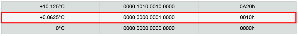
That tells us our absolute minimum value of a single decimal place is 0.0625. Again, this makes sense because we have a maximum of 16 different values that can be returned in our four bits of decimal values… 0x0 through 0xF… 1 / 16 = 0.0625. All we have to do, is take the value of tempLSByte and multiply it by 0.0625.
Almost…
If you look again, you’ll see that the least significant four bits are ALWAYS zero. They’re junk… unused return bits. If we were to just take the highlighted binary example of 0.0625 and put it through that formula, it wouldn’t work because the value is too big… it’s not 1, it’s 16! There are a couple of ways we can handle this. We could use math: take our variable and subtract 0xFFFF from it to eliminate the junk bits, however, I don’t think math is called for here, philosophically. We need to manipulate the bits to build a true value, rather than trying to derive a value from something already valid. That’s why I would prefer to do this mechanically, by shifting the bits, instead. When I come back to look at the code later, I’ll understand that there was something in the returned data that had to be changed, rather than thinking that something within the value had to be calculated. Since the left most four bits are junk, let’s shift our value over by four bits and then multiply it by 0.0625… and adding it to the whole number probably wouldn’t hurt either.
|
1 2 3 |
tempMSByte = Wire.read(); tempLSByte = Wire.read() >> 4; floatTemperature = tempMSByte + (tempLSByte * 0.0625); |
Now we have a fully valid Celsius value to use for our calculations!
Wrapping It All Up
Now we need to take our chunks of code and create a full sketch from them. Remembering some of our guidelines from the code structure module, we’ll need to make sure the following happen…
- A title block
- Include the Wire Library
- Declare constants for things like the I2C address and register addresses
- Call the Wire.begin() and the chip setup function within setup
- Include copious serial debugging as necessary
- Comment as necessary so you’ll understand how it works a year from now
I highly encourage you at this point to take your own knowledge and experience, the chunks of code above, and the datasheet, and build your own sketch. Once you’ve done that, come back and compare it against the completed tested sketch below to see where the differences lie. You won’t derive nearly as much value from simply copying and pasting the code below and uploading it. Try it yourself first!
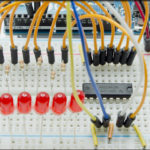
Running the code below will return valid temperature readings from the AT30TS750A on your Education Shield. Remember, the temperature sensor is sitting right on top of the ATMEGA328P that is the brains of your Arduino, so it will probably read back a bit warmer than the ambient temperature of the room you’re sitting in. To test if the code is working, press your finger over this chip…
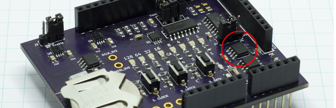
… and you should immediately see the temperature start to climb in the serial monitor. Blowing across the chip will bring the temperature down. Make sure to play with the resolution as well.
|
1 2 3 4 5 6 7 8 9 10 11 12 13 14 15 16 17 18 19 20 21 22 23 24 25 26 27 28 29 30 31 32 33 34 35 36 37 38 39 40 41 42 43 44 45 46 47 48 49 50 51 52 53 54 55 56 57 58 59 60 61 62 63 64 65 66 67 68 69 70 71 72 73 74 75 76 77 78 79 80 81 |
/* A sketch to retrieve the temperature from the AT30TS750A on the Rheingold Heavy I2C and SPI Education Shield. The chip setup function allows the sketch to be easily modified to retrieve the different measurement resolutions that the chip allows for in the datasheet. Website: https://rheingoldheavy.com/retrieving-temperature-value Datasheet: http://www.atmel.com/images/atmel-8855-dts-at30ts750a-datasheet.pdf */ #include "Wire.h" const int AT30TS750_I2C = 0x48; // I2C Address for the temperature sensor const byte REG_TEMP = 0x00; // Register Address: Temperature Value const byte REG_CONFIG = 0x01; // Register Address: Configuration void setup() { Wire.begin(); init_AT30TS750A(); Serial.begin(9600); } void loop() { byte tempLSByte = 0; byte tempMSByte = 0; float floatTemperature = 0.0000; Wire.beginTransmission (AT30TS750_I2C); Wire.write (REG_TEMP); Wire.endTransmission (); Wire.requestFrom (AT30TS750_I2C, 2); tempMSByte = Wire.read(); tempLSByte = Wire.read() >> 4; floatTemperature = tempMSByte + (tempLSByte * .0625); /* DEBUG CODE Serial.print ("Raw Output Byte 01: 0x"); Serial.println (tempMSByte, HEX); Serial.print ("Raw Output Byte 02: 0x"); Serial.println (tempLSByte, HEX); Serial.print ("Raw Output Value 01: "); Serial.println (tempMSByte, DEC); Serial.print ("Raw Output Value 02: "); Serial.println (tempLSByte * .0625, DEC); */ Serial.print ("The temperature is... "); Serial.print (floatTemperature, 4); Serial.print ("C, "); Serial.print ((floatTemperature * (1.8)) + 32, 4); Serial.println ("F"); Serial.println (); delay (100); } void init_AT30TS750A() { /* Change the resolution of the temperature measurement 0x00 = 9 bit resolution 0x20 = 10 bit resolution 0x40 = 11 bit resolution 0x60 = 12 bit resolution */ Wire.beginTransmission (AT30TS750_I2C); Wire.write (REG_CONFIG); Wire.write (0x00); // Set Measurement Resolution Here Wire.endTransmission (); } |
