In February of 2014, I backed the PCBGrip Electronics Assembly System on Kickstarter. It was the first Kickstarter I backed and I was very curious to see what the end result would be, particularly as it wasn’t cheap. I backed at around the $150 level ($159CAD), so I was expecting some pretty heavy duty stuff.
One of the stretch goals for the campaign was to have a parts case provided and true to their word, the parts were all shipped bundled together and placed in a standard parts snap lid parts bin. It’s a really nice case, manufactured in the USA by Plano, and probably for the first time that I have ever used one of these, it came with a surplus of dividers inside to make sure that you could actually organize the parts that it shipped with, without having to resort to cutting file folders apart to make DIY dividers. And let me tell you, there are quite a lot of parts. Some of them are a little small, so getting them back out of the very slick plastic of the parts bin can be a little tricky without needlenose or real fingernails.
[masterslider id=14]Honestly, the parts bin is a “nice to have” from them, as I would have gone out and bought one at the local Home Despot anyway. But having something specifically supplied for the components of the PCBGrip was nice so that everything went from the packaging straight into an organized system. The shipping box was nice and compact with the parts securely packaged – really very well thought out. I use that phrase a lot when describing this to people – well thought through / well though out.
PCBGrip First Impressions
The first thing I noticed as I pulled the pieces out of their packaging and started grouping them together, was the quality of the machining. My god, that is some incredibly beautiful work. Every piece is solid. I mean solid. Things that are supposed to swivel, swivel. Things that are supposed to interlock, interlock. Things that are supposed to fit into other things, do so precisely (with a small exception detailed below). This is all because of two things: firstly the care with which the engineering and design for each parts was done, and secondly, the quality control during the manufacturing process. The guys behind this product did not allow junk to be sent to their customers. I applaud them for that wholeheartedly.
The second thing I noticed is that the pieces are heavy. Not heavy in a bad way, but heavy in the difference between “Husky” brand hand tools and “Snap-On”. This is a tool made of metal – it FEELS like it’s made of metal.
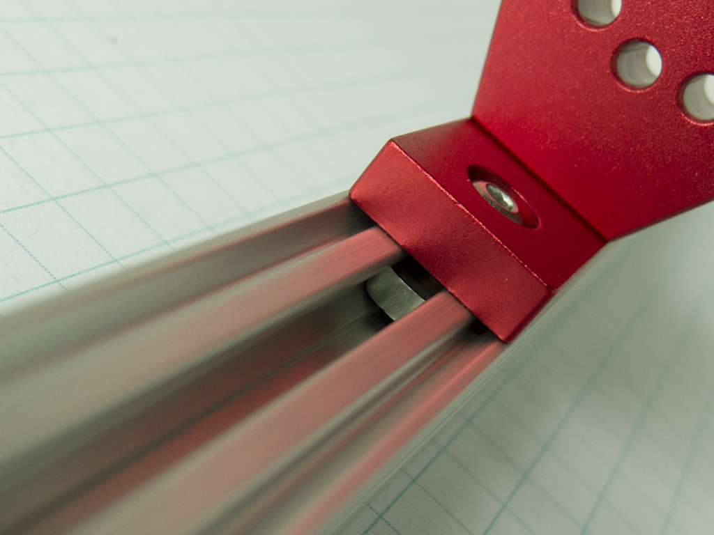
Did I mention how gorgeously machined these parts are? There aren’t any burrs or rough spots on anything! In the pictures to the left, you see the main joining member, that forms the pivot point for the OpenBeam arms, and that thing slid gracefully along it’s track as it was supposed to – you could work on this while wearing an angora sweater and not worry about catching a thread on anything.
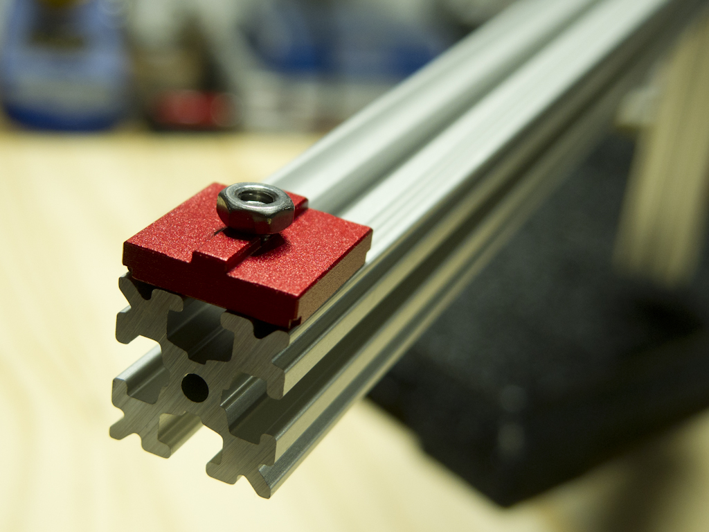
The system works in a way similar to Unistrut, if you’ve ever had the pleasure of working with that. Aside from the very sturdy baseplate, which provides a platform for the main structural bar at the back, the heart of the system is the OpenBeam aluminum extrusion. These are square aluminum bars with channels formed in the middle of each face. Into those channels, you can slide anything that can fit, which in this case means the nuts and screwheads for M3 sized nuts and hex head bolts. This allows you to lock any number of different attachments in place at nearly any location along the extrusion. Guides machined into certain pieces ensure that they lock securely in place with nearly no rotation to speak of. In the picture to the right, you can see a PCB Stand Off laid upside down on a piece of the extrusion – the M3 nut would slide into the channel, with the ridge on the stand off used as a detente to hold it in space squarely.
PCBGrip Hinge Assembly Problem
Unfortunately, the system isn’t perfect – damn close but not perfect. The main hinge point assembles using two screws that pass through the hinge plate and into the large oval piece with the surround of index holes drilled into it, called “Assembly C”. In turn, the hinge plate is then secured to the OpenBeam by fastening two screws through it into a “tri-nut”. The tri-nut slides into the channel and tightening the screws sucks it into a locked position. The hinge plate connection to the OpenBeam is bombproof, however the hinge plate against the “Assembly C” part, relies exclusively on friction between the hinge plate and the “assembly C” piece, and is subjected to quite a bit of torsional force. The result is, that when the pieces are assembled, and you have the large OpenBeam extrusions connected, they act as a lever and make it easy to loosen those two screws attaching the hinge plate to Assembly C. You can see what I mean in the following pictures. Assembly C remains solidly fixed in the main hinge assembly, but the OpenBeam extrusion is still able to rotate around the roll axis (like a propeller) even with everything tightened down just shy of stripping the threads.
[masterslider id=15]To be sure, this is not a fundamental flaw rendering the system unusable, however the whole point of the system is to securely grip your PCB during testing and manufacturing, and I could easily see the base of my hand pressing down on the side of the board while I’m soldering, causing the entire system to shift under that pressure by a centimeter, and maybe the tip of my soldering iron lands somewhere I didn’t intend. Honestly, the problem stands out because everything else, and I mean EVERYTHING, is so well thought through as a system. If they had employed some sort of positive friction lock between the hinge plate and Assembly C, similar to how the stand off plate has the ridge that slots into the OpenBeam, this wouldn’t be a problem.
As I was putting the arms on to form the bars that would provide the work surface for all the clamps, hold downs, etc, I was worried that the entire thing would be too heavy and fall forward, but the base is stable, heavy, and extends forward enough that this never became an issue. Obviously if you rotate the main assembly around so that it’s not centered on the base, then there is a risk of it falling over, but really that would be my fault, not the systems. Further, they thoughtfully machined a section of the base to allow it to be fastened directly to a work surface. I do believe though, that one problem inherent in the system, is that any weight applying downward pressure on the forward facing beams, will cause them to bind up against the beam they are mated to, and not slide fluidly. That’s not such a big deal really, as from my workflow, I would only encounter the problem when slotting in an entirely different board width to work on. If you’re doing production of the same board, it would just pop into whichever mechanism you chose to hold it in place already: spring clips, clamp, whatever.
Multiple Assembly Configurations
Fully assembled, the phrase “there’s no wrong way to use it” holds absolutely true here. Nearly all the pieces can be used with the other pieces, because everything was designed to be used with universal threading, M3 x 0.5 and 3mm rod sizes. A PCB can be clamped into the extrusion, clamped down with bars or spring clipped against the extrusion. All of this allows you to hold the circuit board in whichever manner you need, to allow you to work with a soldering iron, hot air, test probes or even secure a solder paste stencil. For example, take the soldering of through hole pin arrays, or “demon bastard rows of misaligned pins” as I may have referred to them some times. Typically you hold them in place with scotch tape, or putty, or sandbags, or finger tips, while you flip the board over to tack them down on the back of the board, then reflow the solder again and again and again trying to get the damn thing vertical. In this case, you use a little spring tensioned arm to hold the thing in place while you easily flip the entire board over and bam-bam-bam-bam-bam solder the pins in place efficiently. The system I bought ships with enough parts so that I can hold four components in place at a time, which is four more than I was able to manage before.
[masterslider id=16]I initially tried using the spring clip system to hold a PCB in place to see how it would be attempting to solder a surface mount IC down onto a board. The beams seemed to be in the way and I couldn’t get my hands into a comfortable position – there just seemed to be too much stuff in the way. I played with it a little and using the stand offs to hold the board in place with hold downs worked much better, raising the work surface of the board above the level of the beams. The spring heads were so strong though, that they would constantly rotate around the stainless steel rod where they were attached, no matter how hard I screwed down on the respective knurled knob. A little roughening of the surface of the rod should fix that, and as the system wears a bit, it will lock in better.
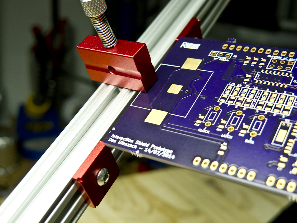
Playing around a little further, I used the clamp system to hold the PCB in place, and I think that really provided the most solid locking of the board with as little in the way of your work as possible, the only caveat being that you lose about a millimeter on either side where the clamp fastens down on your board. Frankly, I lose that much space using my Panavise anyway, so it’s not like this is anything new.
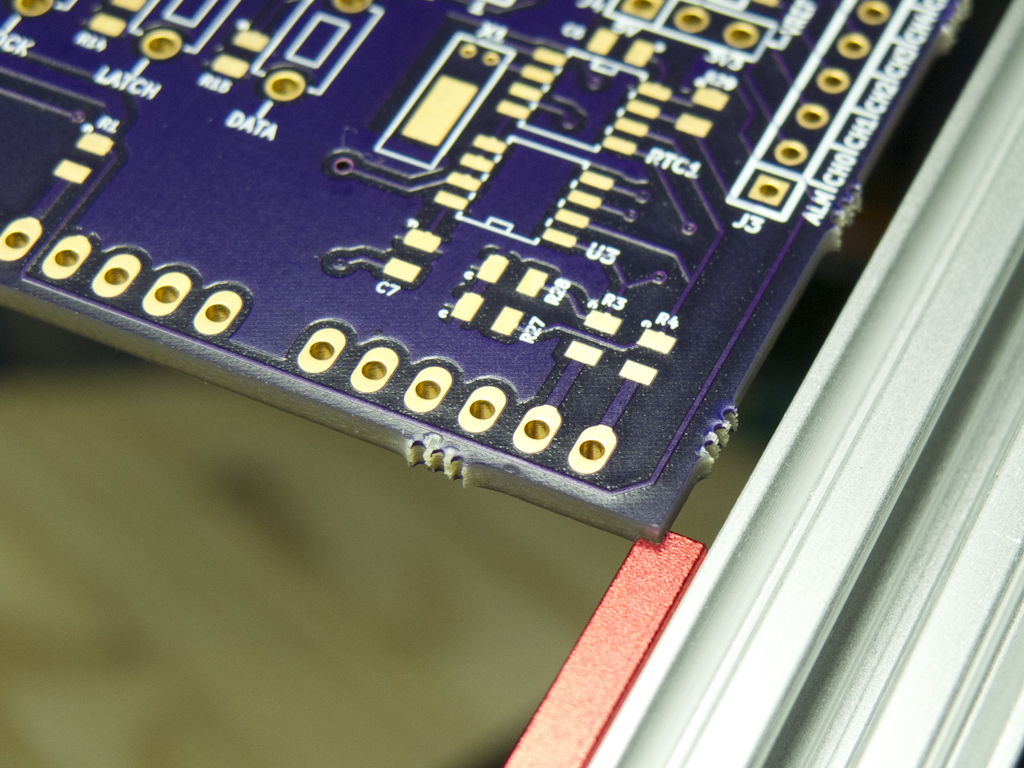
I scuffed up one of the rods a bit that the springhead connects to and it gripped it much more securely, and was able to provide sufficient downward force on a SOIC16 chip, that it didn’t move around when I prodded it with a soldering iron and a pair of tweezers. You can even rotate the entire board with that clamp in place so it’s upside down, and the chip stays firmly pressed to the board, in exactly the same fashion as the through hole piece above.
PCBGrip Wish List
The system comes with a variety of alligator clips to hold things like a super set of helping hands, and they have a link on the Kickstarter page to design files that would allow you to print out a set of clamps for Rigol oscilloscope probes, but I don’t have a 3D printer, and alligator clips are too small to hold scope or meter probes. Some variable clamp system to hold probes in place would be a really nice accessory.
[masterslider id=17]I wish that the OpenBeam bars that extend to the front weren’t as long as the main crossbar in the back. At the very least, it would be nice to be able to purchase different lengths, because the default length takes up a lot of room for a PCB that’s only 50mm x 50mm.
It would be nice if the spring clips could be added to the rods without having to dismantle the rod from it’s keepers. Having a hook shape that slid over the rod with a tightening nut instead of a hole bored through the body of the spring head assembly would make that possible.
Finally, one of the risks with being an early adopter, is that there can be some things not entirely finished: in this case, any documentation whatsoever. I’m a pretty damn handy person, but after going through the assembly of this, I can see how some people feel when faced with putting Ikea furniture together. Thankfully they published a video that shows how the basic system goes together, and how the parts interact, otherwise I’d have been up a creek.
Further, as of this writing, www.pcbgrip.com still doesn’t load, which is a shame. I have to say though, if the choice was between letting a bit of sloppy manufacturing through versus having some snazzy website, I will always land on the side of quality product.
UPDATE 12-NOV-2014: The PCBGrip website is now up and running and also has links to documentation.
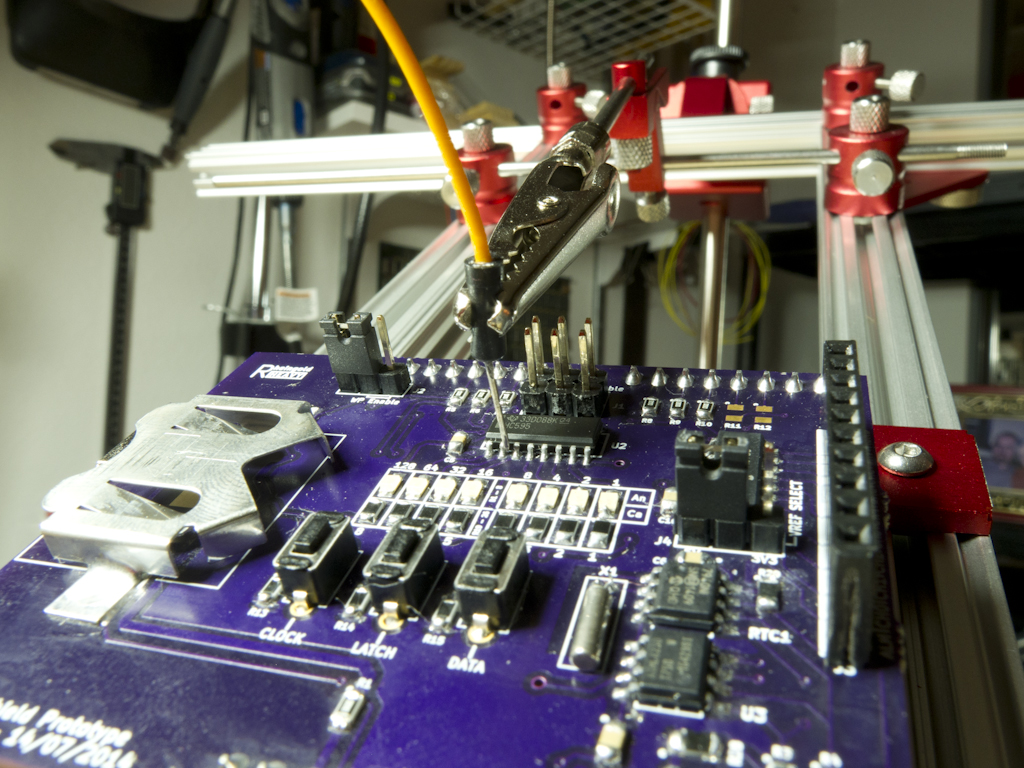
This product is exactly what I’d hoped for, providing a platform for holding either an empty PCB in place for assembly of both SMD and through hole components, and a populated PCB ready for testing. The only problem I really ran into, was the hinge plate assembly, which could easily be remedied on subsequent production runs, and for my current purposes, won’t affect my ability to use it. The components are all well thought out (there’s that phrase again), exquisitely machined, universal and very sturdy.
All in all, I’m extremely happy to have this as part of my lab workbench.
I would also like to thank Jason Green from PCBGrip for his responses to the review. It is very reassuring to know that customer feedback doesn’t fall on deaf ears and he was very receptive to my comments and suggestions, and I’m grateful for his taking the time to troubleshoot the hinge assembly.
