In part 11, the DTR and RESET system was taken apart piece by piece. Now we finally get to wrap up the schematic portion of this project by publishing the ATMEGA328P schematic, the BOM and quickly going through the shield headers.
Build An Arduino UNO R3 from Scratch Table of Contents
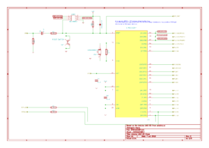
ATMEGA328P Subsystem KiCad Schematic
Compared with how the official schematic looks for this section, I think our ATMEGA328P schematic cleaned it up nicely.
Part Selection
Starting at the top of the ATMEGA328P schematic, the ICSP header is a simple 2×3 header, just like for the 16U2, so we can just that same part again. Same goes for the 10K resistor and the voltage spike protection diode.
The capacitors are all 0.1uF (100nF), so we’ll can keep using the ones that we selected way back when.
The Ceramic Resonator is a Murata CSTCE16M0V53-R0, as specified on the official schematic, and I don’t see a reason to change that. It’s surface mount, includes the load caps, and saves money in the long run. Parts.io shows a risk factor of 2.5, which is juuuust over the line, so I’ll take on that risk in exchange for using a part that I *know* works. The 1M resistor will be a simple 0805 size surface mount chip resistor, 1% tolerance, 1/8W because it’s not going to see any real current, ever.
Rather than use the solder jumper that Arduino employed, I’ve just dropped a 0R resistor onto the schematic instead. I know many people aren’t comfortable with desoldering / soldering surface mount components, so I may change my mind on that later.
The 1K resistors on the serial lines and as the DTR pull down, are no big deal, and I found some good Vishay 0805 resistors to use for that.
The final piece of the 328P Subsystem is the push button. The value noted on the schematic doesn’t help much, but just looking at it shows me it’s not a really technical part. Just a normal four pin tactile button. I’ll go with surface mount, and a nice low height to tuck it down out of the way. I also picked a part with hefty button actuation pressure so it’s not the easiest thing in the world to activate. I think the actuation force required is something like 250 grams? It’s a Panasonic EVQ-Q2U02W.
Here is the ATMEGA328P Subsystem BOM: Arduino UNO R3 From Scratch ATMEGA328P BOM
Arduino Shield Headers
The shield headers should hold no mystery to us at this point. They are the interface we use to get to the pins of the ATMEGA328P either by jabbing jumper wires in there mercilessly, or by attaching a shield to it (the I2C and SPI Education Shield, perhaps?).
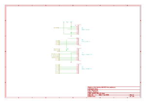
Very quickly, here is the KiCad Schematic I put together…
The headers are a single 6-position female header for analog connections, a pair of 8-position female headers to act as the power connection and first digital pin connector and a single 10-position female header for the other digital pin header.
On the original, they are through hole components, but I don’t see a reason for that. We can use surface mount just as well. I selected 6, 8 and 10 position SMD headers from Sullins Connector Solutions with gold plating on the contacts.
Here is the Arduino Shield Header Subsystem BOM: Arduino UNO R3 From Scratch Shield Header BOM
Next up: The Full Schematic and BOM!
