I think the reason why I love these things so much stems from them being the first IC I ever hooked up to something that worked the first time, out of the box. This was probably due more to the high quality of the tutorial I followed than it is my diligence or talent in making circuits work. One way or the other, understanding shift register basics is critical to understanding serial communications.
Starting off with shift register basics: a shift register is a device that takes a serial input and converts it into a parallel output (there are shift registers that go in the other direction but let’s stick to this definition for now). Think of it like a key sliding into a lock – you’re sending in the value of that key, the series of peaks and valleys on the edge of it, sequentially. When you turn the key, you’re sending the entire value at once, sending the value in parallel, to open the lock. With a shift register, you feed in a series of ons and offs sequentially, then you use the entire value at once by outputting it on the pins of the device.
A register is a chunk of logic memory. As an example, a 74HC595 is an 8-bit shift register, meaning that it has a memory register 8-bits wide into which you can send data – you tell the shift register, one at a time, what the state of it’s outputs should be, and then when you’re done, it sets the outputs to their respective states at the same time. The “shift” part of the name is important too though. It means the data inside gets shifted out sequentially as new data is sent in, like a tickertape machine. If you have 8 bits in the register already, and you send 8 new bits in, you’re replacing all the old data with the new data. If you only send in 3 bits though, you’ll still have the last 5 bits from the previous data set in there, but shifted over 3 spaces by the new chunk. Have I confused you yet?
We’ll go into the mechanics of how this happens in a second, but let’s look at that first example…

You have 8 bits already in the shift register: alien, alien, smiley, smiley, alien, alien, alien, alien. Now you want to store another full 8 bits of data in there, so we push the old data out to the right with the new data coming in from the left, leaving us with the new register value.
Now for the second example…

Here, we are only sending in three bits of data: smiley, smiley, smiley. This has the effect of shifting three aliens out the right side, leaving us with the new pattern.
The direction the data goes in, from the left or from the right, is set in code by specifying either the “most significant bit” or the “least significant bit” as the first bit that will be shifted out. The examples above both show least significant bit shifting.
Each new bit in, pushes one old bit out.
All of this bit shifting is controlled using three primary signals: data, clock, and latch. Additionally, there are three other pins that can be used to affect changes: clear, enable and serial out. Now, for purposes of trying like hell to confuse the populace, every manufacturer has decided to name these things differently. To whit, a sampling from datasheets I found through Digikey…
| English | T.I. | Fairchild | NXP | Diodes Inc. | On Semi | ST Micro |
|---|---|---|---|---|---|---|
| Data | SER | SER | DS | DS | A | SI |
| Clock | RCLK | RCK | STCP | STCP | SHIFT CLOCK | RCK |
| Latch | SRCLK | SCK | SHCP | SHCP | LATCH CLOCK | SCK |
| Clear | SRCLR | SCLR | MR | MR | RESET | SCLR |
| Enable | OE | G | OE | OE | OUTPUT ENABLE | G |
| Serial Out | QH' | Q'h | Q7S | Q7S | SQh | QH' |
So, then. The device actually has two memory banks, the SHIFT REGISTER and the STORAGE REGISTER. The way this works, is, you transmit the values you want the device to have on the data pin, but the shift register needs some way of knowing how to sequence that data, and that’s what the clock pin is for. Whenever the clock pin goes high, the state of the data pin is shifted into the SHIFT REGISTER.
Can you tell what this sequence translates to?

Does that long high period in the middle count as one bit? Four bits? Well, let me add a clock signal to help clarify…

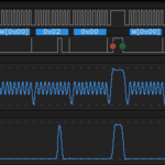
It’s actually three bits! Every time the clock goes high, that’s when you interpret the current state of the data line, and that’s what gets pushed into the shift register. So this sequence translates to B00111010. For confirmation, let’s have a look at what the oscilloscope displays when using the shiftOut(dataPin, clockPin, MSBFIRST, B00111010); Arduino command.
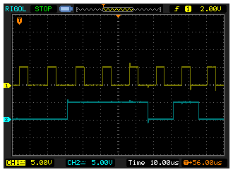
Shift Register In Action
The yellow trace is Channel 1 of the oscilloscope, and is tracking the CLOCK signal. The blue trace is Channel 2 and is tracking the Serial Data line. You see eight pulses on the clock line, one for each bit of data, and you see the corresponding B00111010 being transmitted on the SERIAL DATA input.If you were to widen out the view of that window a little bit, you’d see that the CLOCK and SERIAL DATA lines were both at ground before and after the data was transmitted into the shift register using the shiftOut command.
We’ve stored the value we want in the chip, but for that data to be moved to the outputs, you need to bring the latch pin high, which commits whatever the value is in the SHIFT REGISTER to the STORAGE REGISTER. You can shift data all day long in and out of the SHIFT REGISTER, but it will never be displayed until you toggle the latch at which point whatever is in SHIFT gets put into STORAGE.
Those other pins though, have value to you as well. The clear pin sets the value of the shift register to B00000000, blanking it out. If you toggle the latch when you take the clear pin low, you blank the outputs. The enable pin, drives the outputs from fully on, to a high impedance state, meaning they basically don’t exist as far as the circuit is concerned. Both the clear and enable pins are active low, meaning that they do what their name says they do, if they are at 0V. In most cases where I’m just playing around, I just tie clear to 5V and tie enable to GND, making their states permanent. You can send a PWM signal to enable though which lets you do things like seemingly dim any LEDs connected to the outputs.
The final pin, Serial Out, is used to daisy chain shift registers together. If you only have one shift register and you send it a sequence 12 bits long, the first four bits are lost because they will get shifted out as you clock in the last four bits. If there’s a second shift register though, the overflow goes into the second shift register, basically expanding you from 8-bits to 16-bits. The datasheet will tell you how many you can conceivably connect, Serial Out to Data, before you start having signal degradation.
