In April-2014, I backed the SparkFun MicroView, developed by Geek Ammo on Kickstarter. I’ve grown out of my “oooo shiny!” phase for the most part, and really try to focus on bringing things into my lab that I think will either teach me something, enable me to teach someone else something, or provide a new (hopefully better) way of getting something done. As a product, the MicroView ticks off all those boxes, although the ecosystem around it is frustratingly still under development.
MicroView Overview
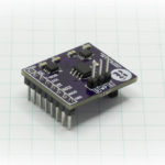
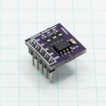
At it’s essence, the MicroView is a teeny-tiny fully functional Arduino with an OLED screen on top of it. Due to the size, it is somewhat pin limited, so in Arduino speak, you have six Analog pins and six Digital pins. Three of the pins are PWM capable, and include the two interrupt pins (Digital 2 and 3), Serial Tx/Rx (Digital 1 and 0) and the I2C Bus pins (Analog 4 and 5). In addition, you have RESET, GND, +5V and Vin. It’s very apparent that careful decisions were made as to which pins to sacrifice and which to provide, as there are sufficient quantities of PWM, interrupt and timer pins available to accomplish most tasks.
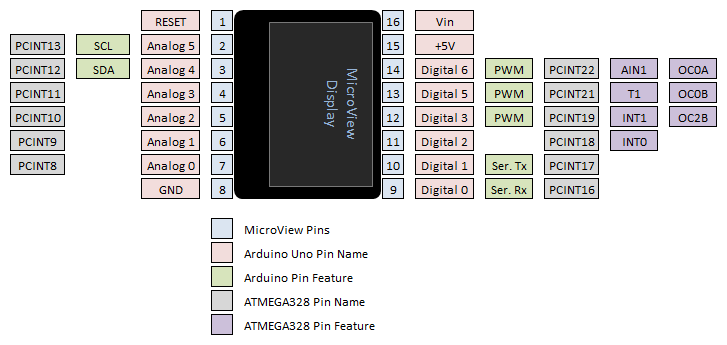
The star of the show is quite simply the OLED display. No need to hook anything else up to this beasty to get immediate feedback from your circuits; no LCD backpacks, no seven segment displays, no LED grid arrays charlieplexed to hell and back… you have a postage stamp sized 64×48 pixel display that is directly addressable by code, ready to go, right away. Frankly, it’s pretty awesome. The color is slightly deeper blue than the somewhat greenish-blue-cyan color that you see in the pictures here, and very bright and easy to see, even under the bright light on my magnifier.
MicroView First Impressions
 I pledged at the “Blinking Eyes” level: two MicroViews and one FTDI programming breakout board. As is customary, I set my “pledge” on Kickstarter and then promptly let myself forget about it for several months, because you’re not going to get product right away, and I’m okay with that.
There’s always a bit of worry with the “I backed the project and now I’ll never hear from these guys again,” but I really liked the level of detail in the updates they provided during their run to production, and I had no problem with the infamous “$58,000” testing mistake that SparkFun had. Mistakes happen, delays happen. I was confident throughout that it was only a matter of time before what I was waiting for would be delivered.
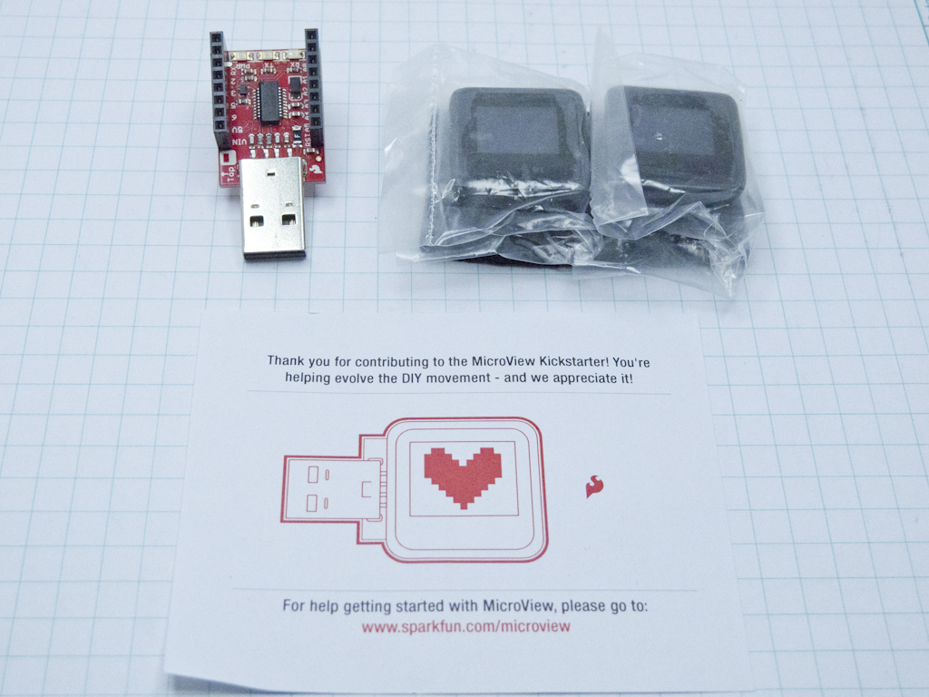
 It arrived early October, and when you open your box, you have your MicroViews in plastic and jabbed into ESD foam and the FTDI programming breakout board. There’s also a cute little note telling you, basically, any and all documentation can be found at http://www.sparkfun.com/microview, but more on that later.
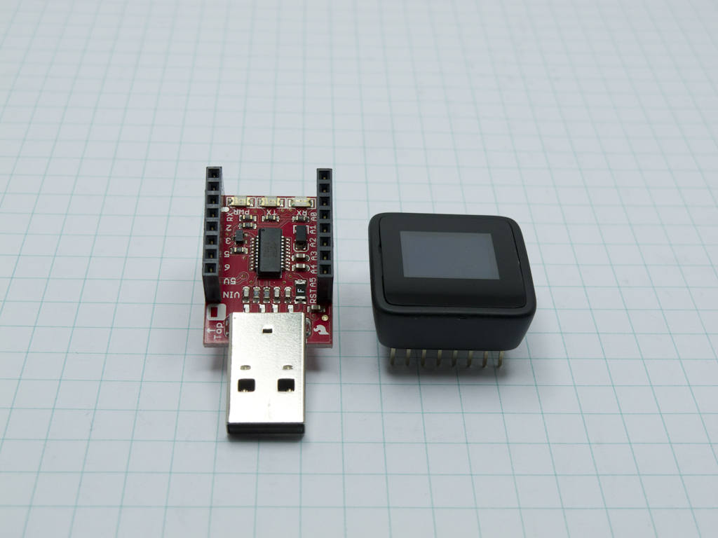
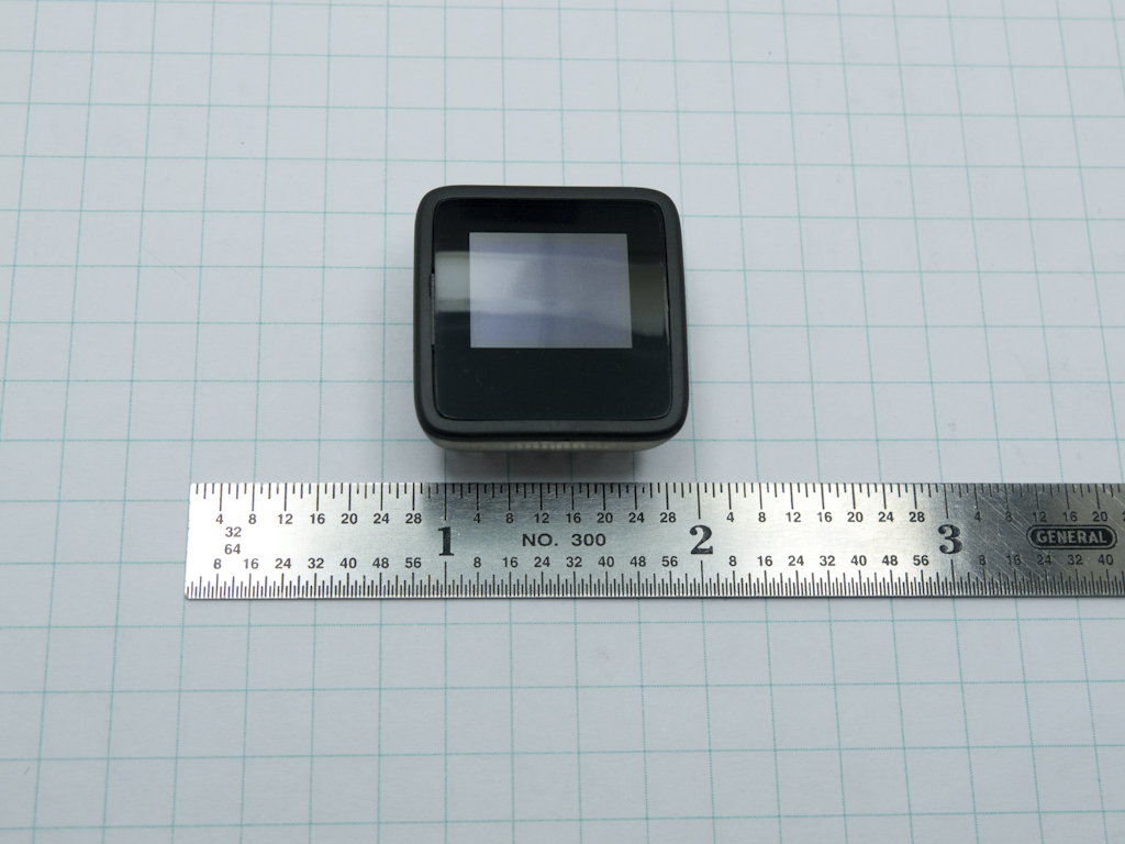
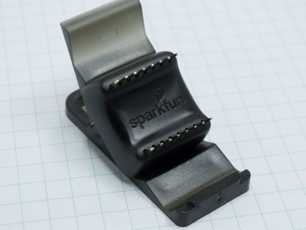
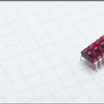
The unit itself is very sleek and weighs less than 10 grams. The plastic body is uniform and very smooth, with barely any tooling marks. Of the two I have, one is entirely blemish free, and on the top of the other, there is the barest hint of a flat blade screwdriver gouge mark on the case, where I suspect someone at SparkFun had to pry it open to resolve / test the bootloader issue before it shipped. So what, as products, they are gorgeously designed. They have a very clean look and feel, that really gives the impression that the designer took their time. There’s isn’t a hard 90 degree edge anywhere on the thing.
[masterslider id=24]
The technical side of the device has a .1″ pitch header arranged in two rows of 8 pins each, separated at a distance of .7″ between the two rows. This mates perfectly with either a standard breadboard or the FTDI header, which also has pins to match a breadboard.
Turning It On and Getting It Working
Getting the device connected so you can start programming it and playing is straight forward… or is it? You just plug the MicroView into the programming header, plug the programming header into a USB cable and boom! Off you go.
Nope.
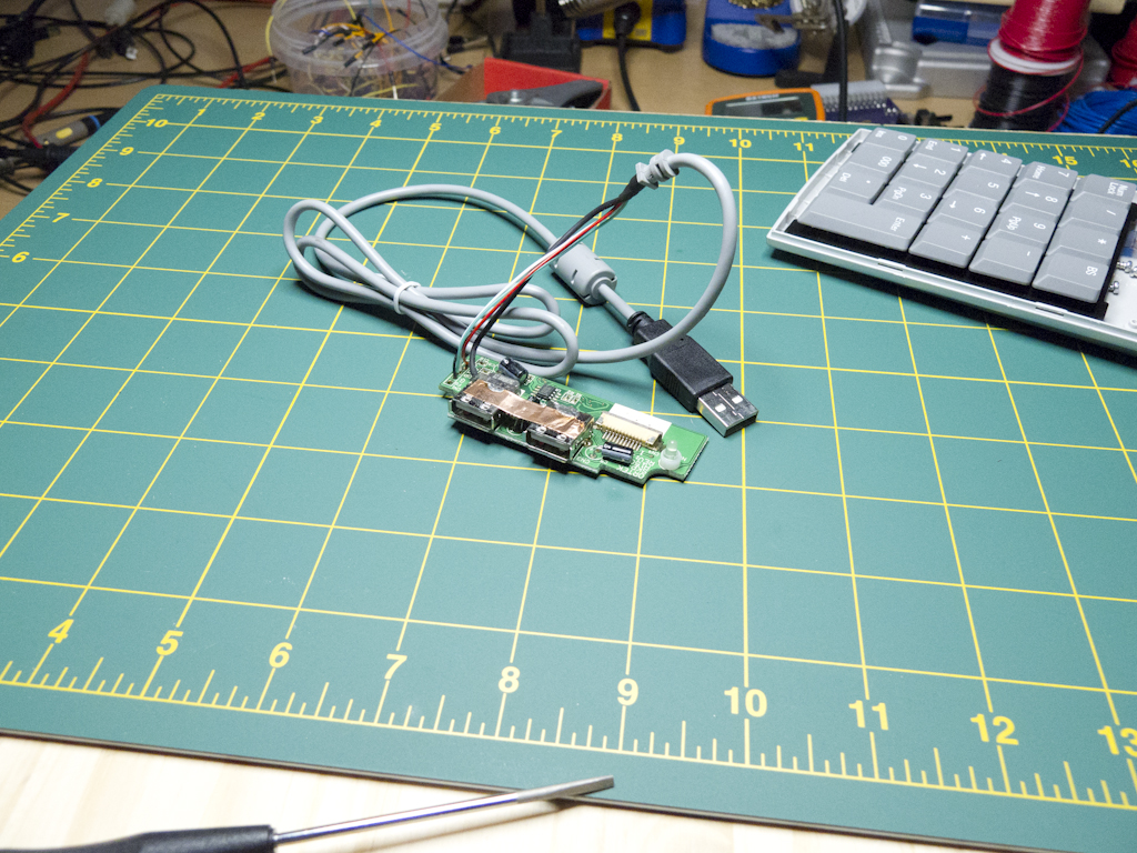
The programming header has a USB 2.0 Type A plug on it… not a jack. So you can’t plug it into any of the 1000 USB cables you have that shipped with every piece of electronics you’ve bought in the last 10 years, you have to plug it directly into your laptop or desktop. If you program from a laptop, then bully for you. I don’t. I have a desktop that is actually a deskunder with no available frontside USB ports, and I’ve got the back USB ports plugged full of cables to bring them topside into my oscilloscope, my dev boards, cameras, etc. etc. Essentially this is entirely the wrong connector for me to have on a device that I want to be able to see while I work on it.
It was also 7:54AM this morning when I got to this point, so it’s not like I can go anywhere to get an adapter.
*** Time Passed ***
Well, it’s not like I ever really used this 10 key anyway…
Adapter cable now ready, I went to the URL listed on that cute little note. This is where I would begin having problems with the thought process behind the ecosystem. That page is the product page at SparkFun. I’ve already purchased the thing — I don’t need that page — I need the page that tells me how to use the thing. After a little scrolling, you find links to “Learn MicroView”, “Product Video”, “Demo Video” and “MicroView Bootloader Installation”. I went to Learn MicroView. Essentially, I wanted to make sure that I didn’t need to do anything else first before I tried plugging it in. I was actually R’ing TFM.
Right at the top of the page was the Quick Start Page that would help me verify that I have everything I need. So I went in there and sure enough, just plug the FTDI programmer into the breadboard, and the MicroView into the programmer (making sure pin 1 goes where it’s supposed to), and then plug it in.
Immediately a demo started playing, cycling through a number of different graphic capabilities of the MicroView and I was reminded why I was so keen to play with the thing. It’s clean, it’s fast, it’s bright and it’s high resolution. The demo started playing RIGHT away too, no warm up time, nothing. Then, out of nowhere, it asked me to connect a 330Ω resistor across pins 5 and 8. I thought that was odd… did it want me to short something and intentionally burn a fuse to enable / disable something? I fished out a resistor and it thanked me and then asked me to connect it somewhere else… then somewhere else… then a 10K resistor… then the 330Ω one again, then an LED. Then it blinked the LED once and went back into the demo.
Turns out that was some kind of tutorial. In the Quick Start page it’s called “MicroView Teaching How To Use MicroView.” Except, it’s not teaching me anything about how to use the MicroView, it’s making sure I know how to plug resistors into the breadboard. I was very confused.
To be fair, I did learn one thing about the MicroView through the whole “do you know how to plug something into something” process – it takes up a LOT of room in it’s region of the breadboard. Trying to connect the 5V pin to the power rail involved flipping the thing back and forth, trying to determine with my crappy eyesight if I was actually, ACTUALLY selecting pin 2. Then I moved the entire thing to the end of the breadboard so at least the breadboard numbering would match the pin out. There isn’t any silk screening or embossing on the case of the MicroView to help figure out which pin is which. When looking directly top down on the device, you only see one column of breadboard sockets above and below, and only two columns are accessible. It almost needs a breakout board so you can offset the MicroView to one side of the board just to see where it’s plugged in.
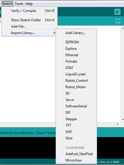
 Duly impressed by the demo, if befuddled by that little tutorial, I started trying to figure out how to program it myself. The QuickStart page isn’t of any use here, but the Getting Started with MicroView page is. I went through the documentation to install the MicroView library and add it to the list of boards in the Arduino IDE. They push the use of CodeBender quite a bit throughout the microview.io site, which is OK, but I’ll stick with my IDE.
It’s important to emphasize that this isn’t a display backpack for your Arduino Uno. It is an Arduino, physically melded with a graphics display on top. You write and compile code for it right in the same development tool you would use for an Uno, a Mega, a Pro Mini, whatever. The Arduino Bootloader is waiting on the Atmel chip waiting for you.
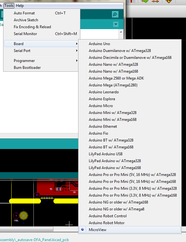
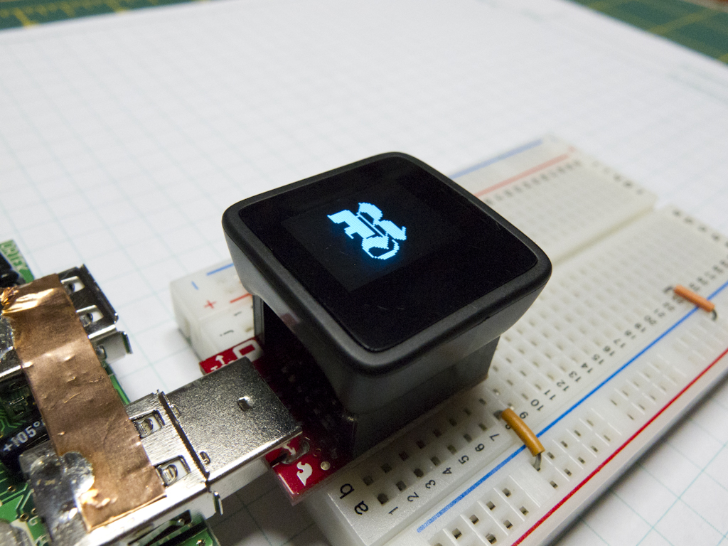
I opened the Arduino IDE, selected the MicroView board, and wrote the recommended Hello World! sketch.
|
1 2 3 4 5 6 7 8 9 10 11 12 13 14 |
#include <MicroView.h>; void setup() { uView.begin (); // start Microview uView.clear (PAGE); // clear the page uView.print ("HelloWorld'); // display "HelloWorld" uView.display (); } void loop() { } |
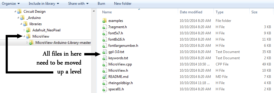
When I tried to compile it though, I got errors saying that “uView was not declared in this scope”.
Turns out the zip file downloaded from the MicroView Library Github Repo, contains a subfolder called “MicroView-Arduino_Library-master” that needs have all it’s contents moved up a level in order for the library to function after you import it. I suspect this is something that GitHub does, and it’s just a quick change to the documentation for this to be a totally smooth process.
Once the library issue was fixed though, it worked like a charm.
Moving Past the MicroView Demo Screen
Eager to try more, I went to the MicroView website hoping to grab more example code, or read some tutorials. There is an entire “Learning Kit” area that I thought would do the trick, but it only contains beginner electronics tutorials. I did find that importing the library imported example code though, so I had a look around at that to see if I could figure out what’s going on.
The non-learning-kit examples are clean, but not commented, so it’s a little difficult determining exactly what parts of the code are prerequisites for setup, and what parts of the code are where you can tinker. In the tops of the example sketches, I only found one title comment block that actually described what the code did (3D rotating cube), the rest only contained stern looking GPL language. Reading through their library documentation, I couldn’t find an obvious way to brick the thing by accident, so the worst you would experience is code that just doesn’t run or display right. Still, some comments in the code would have been very helpful. I have learned that you need uView.begin() in your setup, but I only figured that out because it’s in every one of the examples, not because I read documentation anywhere that said, “This is how you structure a MicroView compatible sketch.”
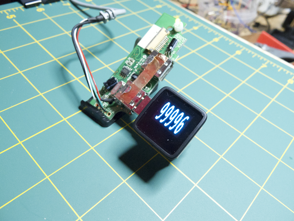
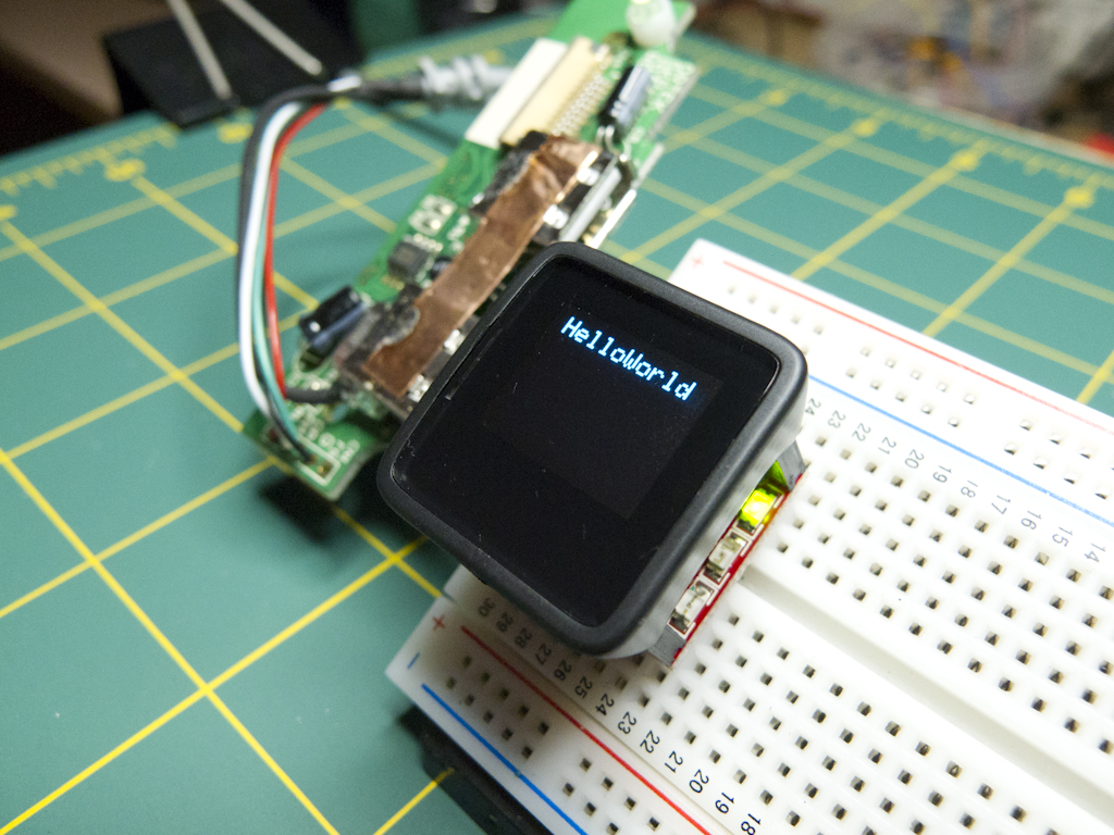
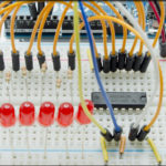
I figured it would be easiest to throw a quick little light dependent resistor circuit together and build a brightness meter, then have the MicroView display the ADC value. Again, there’s no plain English “this is how you use the MicroViewWidget Class” tutorial or page, so you have to hack the code yourself and read through the class reference in the library documentation which is definitely technically detailed but not overtly friendly. As a test, I just loaded up a sketch that read the ADC level to the serial monitor and that worked a charm right off the bat, so the Arduino brain in the thing was working perfectly. I just had to figure out how to make the display dance. Fortunately, Circuit 05 in the Learning Kit also works with an LDR, so I was able to use that code as a starting point.
|
1 2 3 4 5 6 7 8 9 10 11 12 13 14 15 16 17 18 19 20 21 22 23 24 25 26 27 28 29 30 31 32 33 34 35 |
/* A simple brightness meter to practice using the display of the SparkFun MicroView. It uses a light dependent resistor with a 10K resistor connected in series as a voltage divider, and sends the midpoint voltage to the Arduino ADC on Analog pin 0. http://www.rheingoldheavy.com */ #include MicroViewWidget *widget; // Declare widget pointer int analogLDRPin = 0; // The pin on which we will sample the LDR voltage int brightLevel = 0; // Holds the value of the LDR reading void setup() { uView.begin (); // Start Microview uView.clear (PAGE); // Clear the page widget = new MicroViewGauge(32,24,0,1023,WIDGETSTYLE1); // Create a Style 1 Gauge widget // Serial.begin(9600); // Uncomment for Serial debug } void loop() { brightLevel = analogRead (analogLDRPin); // Sample the voltage at the LDR widget->setValue(brightLevel); // Set the gauge widets value to brightLevel uView.display(); // Display the widget // Serial.println(brightLevel); // Uncomment for Serial debug // delay(100); // Uncomment for Serial debug } |
In operation, it’s soooooo cool. As you brighten or darken the shadow over the LDR, that dial on the meter moves in real time. It’s very frustrating though that no where in the documentation does it clearly spell out what the different widget styles look like. A screen capture for each would have been nice, or even ascii art, man.
The bottom line with the documentation is that I, personally, would have preferred to have had my hand held a little more rather than have to slice and dice my way to displaying a sensor reading. I thought I would find it in the “Learning” section, but that is dedicated to teaching what a resistor does, not a MicroView. I eagerly await more from the MicroView team in this area.
In an effort to help, I’ve written a MicroView Widget Style Guide entry in my lab notebook to keep handy for the future.
How Open Source is the MicroView
The entire library is available on the MicroView github repo, as are Eagle schematic and board files for both the MicroView itself, and the USB programmer. Hell, they even have STL files up there so you can print your own enclosure if you have a 3D printer. They haven’t published Gerbers or BOM files for either board, but that’s to be expected. You can generate both from Eagle, and you really would need to source the components yourself anyway, so if they had something with full part numbers for each distributor listed, you’d wind up having to do research anyway.
Honestly, there was more on their repo than I expected, and that’s good. The molded enclosure is fantastic for the MicroView as a product in and of itself, but it would be difficult to incorporate it into anything else. Having the schematic and board files allows you to roll your own if you have the skill and so choose. In my case, I do have the skill and I will most likely choose to do so!
Bottom Line
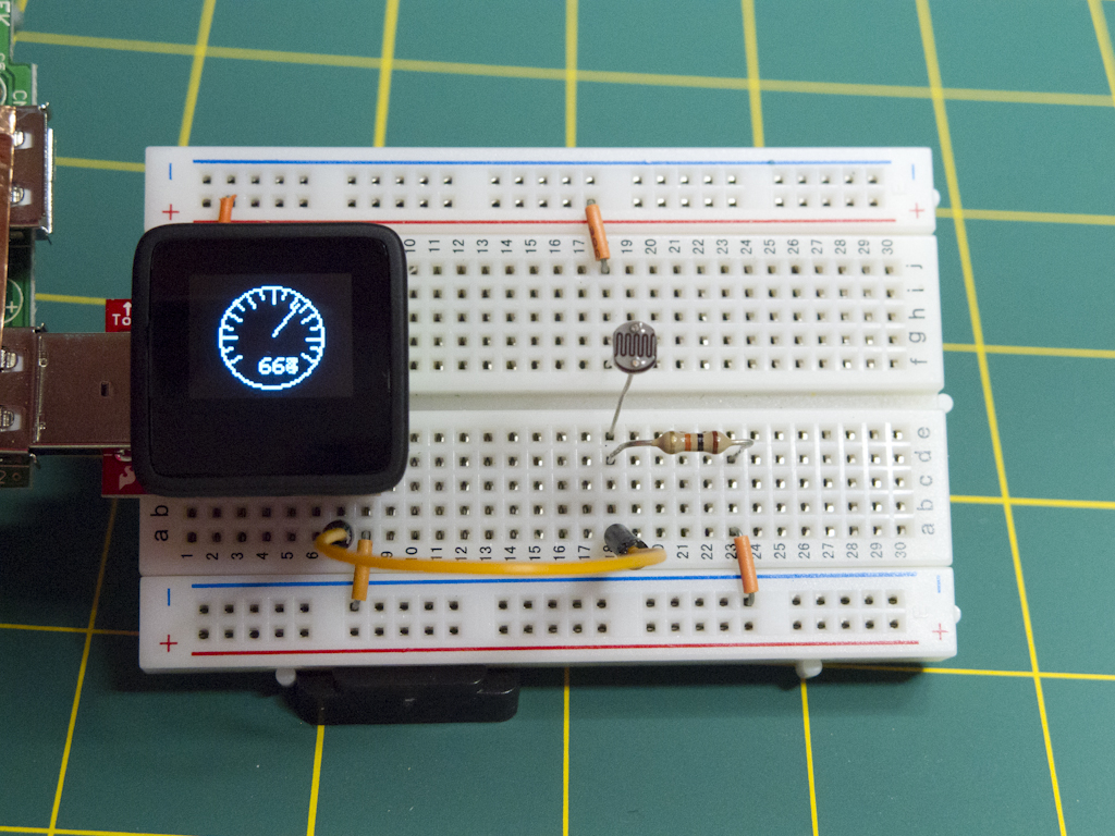
I love this thing. It’s just neat. I followed the more advanced tutorial on importing custom fonts into it, and that’s how I generated this…
… and the idea of being able to scroll, animate and add sprites on the display is very exciting. However the methods it provides to visualize data are the real attention grabbers for me. It’s like a Ferrari compared to my Display Board Citroën 2CV.
As soon as the documentation catches up with the quality of the component, I’d consider the MicroView to be one of the premier Arduino compatibles on the market..
