This Snowbot Assembly Guide will help you put together the Rheingold Heavy Holiday Project: The 2015 Snowbot Rev1.
Snowbot Assembly: PCB
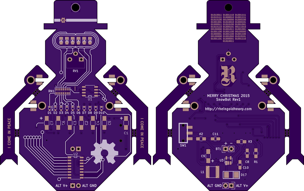
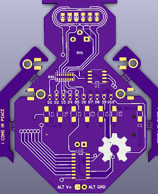
When you receive the PCB, it should look something like this (assuming you used OSHPark). The arms will still be attached to the body of Snowbot by the little 3-drill mousebites at the bicep and forearm areas of the arm. It’s up to you if you want to detach them and solder them in place, it’s purely cosmetic.
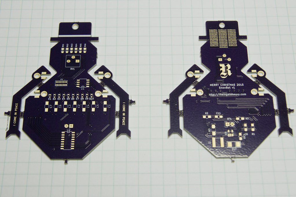
Please note that I have added polarity markings to the PCB that don’t appear in the graphics below. The following image shows the corrected silk screen that is associated with the gerber files and OSHPark project.
Snowbot Assembly: Mounting The Arms
I don’t recommend soldering the arms into the slots until all the rest of the board is done, because they make laying the board down on your work surface impossible. If you do want to snap the arms off, it’s best to give them a snip with your side cutters or diagonal cutters. There should be enough room to get the tip in to make the snip. I just worried each arm off by gently pressing back and forth until they stressed enough to break easily. You’ll want to sand or file the edge down smooth, but you’re sanding / filing fiberglass (the FR4 insulating material of the PCB sandwich), so make sure you don’t breath any of the dust.
The arms are mounted into the slots using something called Sheadel Joints (named after all around awesome OSHPark guy @tekdemo). The idea is to slide the arms into their slots and then solder them in place by flooding the area where the surface pad and the through hole drill intersect. No need to be fancy about it, just feed the solder in until it starts to bead up. Super easy, and super strong.
Snowbot Assembly: Back Side – Boost Converter
The entire back side of the board is dedicated to converting the 3.7V LiPO battery voltage to 5V for use by the components on the front of the board. I think it’s best to start with the power section first, so that you can test it with a LiPO and make sure it’s outputting +5V. When you’re done assembling the power circuit, you can use the ALT GND and ALT V+ as test points.
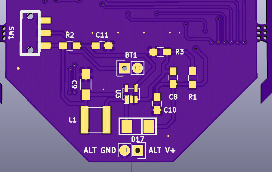
I recommend starting with the boost converter, U3, and spiraling your way out from there. When I built the prototype, I followed this order…
- U3 – SC4503 Boost Converter
- C10 – 10uF
- C9 – 4.7uF (positive towards bottom)
- C8 – 10pF
- R1 – 187K
- R3 – 60.4K
- C11 – 56nF
- R2 – 15K
- SW1 – Power Switch
- L1 – 1.5uH Inductor
- D17 – 10BQ015 Diode (cathode towards right)
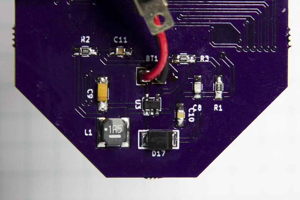
The order isn’t too terribly important except for soldering L1 before D17. You’ll really need to get in and move your soldering iron around to spread enough solder on that big inductor pad, and it’s much easier without the diode in the way. With the inductor finished, placing D17 is a piece of cake.
This is what the completed back side layer looks like on the prototype. It looks a little different because I added the power switch footprint and alternate voltage header on the revised design.
Snowbot Assembly: Battery Connector
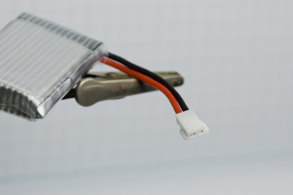
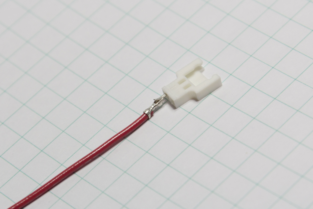
I based the design on the use of LiPO batteries I found on Amazon: a four pack of 680mAh LiPOs complete with a cheap charger. They included a knockoff brand version of a standard Molex connector, and look like this…
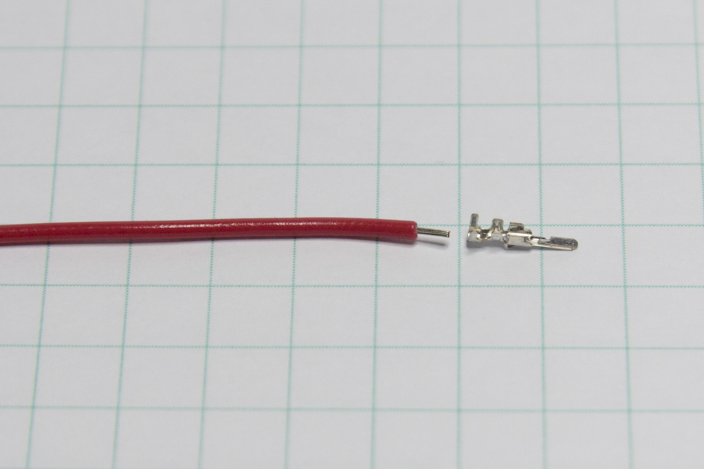
The BOM file contains the male pins and matching shroud to allow you to connect the battery to another wiring harness, which in turn would be soldered to the PCB. The only pins that are available are crimp pins though, and I don’t think any of us wants to spend $30 on a Molex crimping tool. I used a pair of needle nose to do it, with 24 AWG stranded wire.
Strip off about 1/4″ / 1cm of insulation from the ends of your wires. DO NOT TIN THEM.
Slide that into the valley of the pin, so that the outer most crimp legs are against insulation.
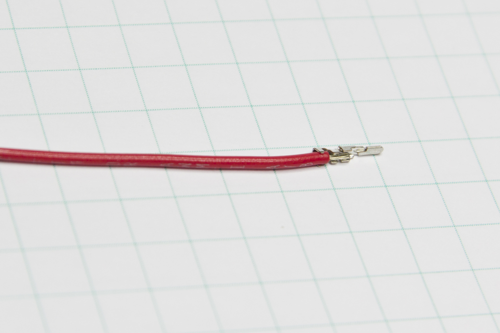
Use the needle nose pliers to carefully fold the legs over the insulation and strands of wire. Don’t just mash them together. The legs need to be laid down over the insulation and wire so that it can be pressed successfully into the shroud. Additionally, towards the front of the pin, there is a little raised detente that needs to remain raised as that is what will eventually secure the pin in the shroud. This is by far the most annoying part of the whole build.
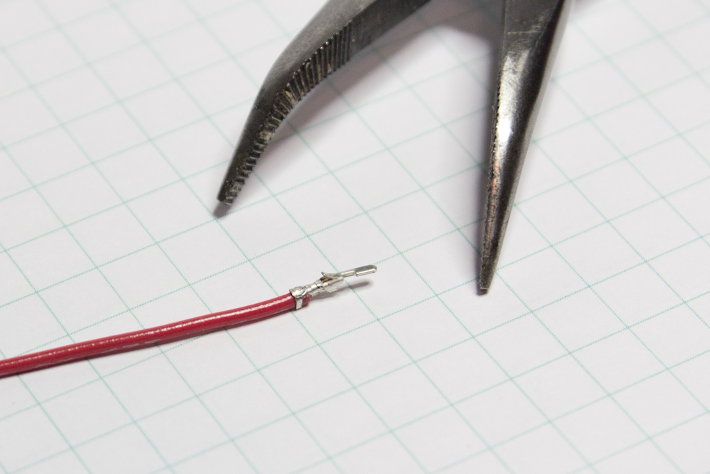
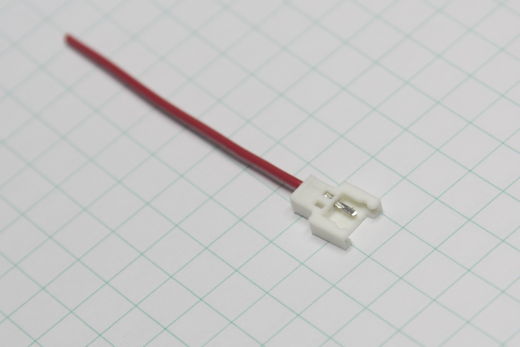
Carefully insert the pin into the shroud, making sure the raised metal flap is facing up on the pin, and the opening in the shroud into which it will fit is facing up too. Push the pin in slow and carefully so you don’t bend anything… it needs to go in straight and flat.
Eventually, you’ll have enough peaking through that you can grab the tip of the pin with the needlenose and pull it the rest of the way home. You’ll probably bend the pin upwards a little in the process, but it’s remarkably durable, so just bend it back once the metal flap seats into the opening.
As you’re assembling everything, be very mindful of where +V and GND are supposed to be!
Remember, if you want to attach a different sized battery (tested up to 9V), you can use the alternate power header at the bottom of the board. The VCC level needs to be at least 5V (the output level of the power regulator circuit), in order for the capacitors to time correctly, and to overcome the multiple diode voltage drops.
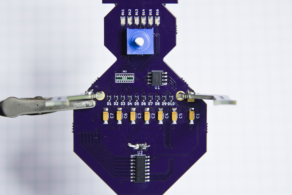
Snowbot Assembly: Front Side – Larson Scanner
The front side of Snowbot has all the circuitry to make the Larson Scanner. If you’re already comfortable with surface mount soldering, then there isn’t anything on their that should pose a challenge.
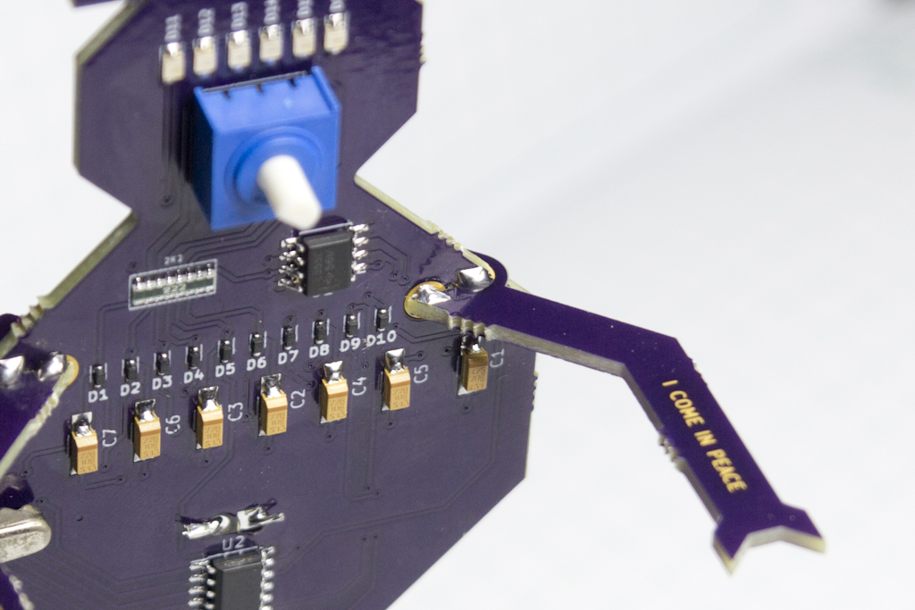
The toughest part is ensuring you get the diodes D1 – D10 in the correct orientation, with the cathode facing towards the top of the board. They seem like very small parts, but no more difficult to solder than an 0603 capacitor. I highly recommend soldering them in place before anything else, so that you have all the room you need to work on them.
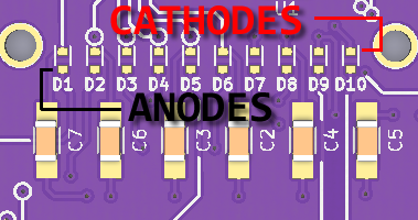
With D1 through D10 in place, You can solder down pretty much everything else at will. I made sure there was loads of room around each component. Note that the LEDs that form Snowbot’s eye are also mounted with the cathode towards the top of the board, and the anode towards the potentiometer.
Similarly, the tantalum 22uF capacitors are polarized as well, and need to be placed with their positive end towards the top.
The 2506 footprint resistor network can be a little squirmy to place, since it’s long and thin. Just use the usual “tack a corner down with solder, and drag solder the other side with a lot of flux” technique and it’ll do just fine.
The front of the board should look like this when completed…
Snowbot Assembly: Success!
When you’re done soldering, connect the battery and slide the power switch and you should see the LEDs start to scan back and forth at whatever speed the potentiometer is set at. Twist the knob of the pot back and forth and you should see the speed of the chasing LEDs adjust accordingly, with that silky smooth fade from the capacitors.
If you have any questions, don’t hesitate to send an email to support, and remember to post a picture of your Snowbot on twitter!
Good luck!!