Welcome to the Rheingold Heavy I2C Display Add-on. This functionality overview will help you get acquainted with the features of this product. We designed this circuit board to work as an independent display capable of helping you to visualize data that you’re receiving from sensors. It works exceptionally well with the I2C and SPI Education Shield .
Objectives
- Understand the various operating characteristics of the I2C Display Add-on.
- Understand what the connection requirements are for compatibility with various microcontrollers.
- Identify the different subsystems on the board.
- Understand how to connect the display to your microcontroller.
- Understand how to use the multiplexer.
Background
I2C Display Add-on Product Page
AS1115 Datasheet
Setup
There is no setup required for this module.
I2C Display Add-on Operating Characteristics
The I2C Display Add-on is designed to work with any 5V I2C compatible microcontroller, with the Arduino UNO specifically used during development. The main IC, the AMS AS1115 is able to run at 3V3, however the current setting resistors were selected with a 5V VCC in mind to power the 2VF / 30mA LEDs, and the reduced voltage would consequently result in a significantly lower maximum brightness. No harm would come to the device by doing so however.
| Min | Typ | Max | Units | |
|---|---|---|---|---|
| Operating Voltage - Display Add-on | 5.0 | V | ||
| Operating Voltage - AS1115 | 5.0 | V | ||
| Operating Voltage - Piezo | 5.0 | 30 | V | |
| Vf - Seven Segment Display | 2.0 | 2.6 | V | |
| Vf - Red LEDs | 2.0 | 2.4 | V | |
| Vf - Green LEDs | 2.0 | 2.4 | V | |
| Current Draw - Seven Segment Display* | 25 | 90 | mA | |
| Current Draw - Red LEDs* | 30 | mA | ||
| Current Draw - Green LEDs* | 30 | mA | ||
| Current Draw - Single Segment | 0.6 | 1.6 | 2.3 | mA |
| Current Draw - Single Red LED | 0.6 | 1.6 | 2.3 | mA |
| Current Draw - Single Green LED | 0.6 | 1.6 | 2.3 | mA |
| Current Draw - All On | 8 | 60 | 100 | mA |
| Current Draw - All Off / Shutdown 0x81 | 0.5 | mA | ||
| Current Draw - All Off / Shutdown 0x80 | 0.1 | 0.1µA | ||
| Clock Frequency I2C | 100 | 400 | kHz | |
| Clock Frequency - Multiplexor | 0.49 | 79 | kHz |
*Values published in respective manufacturer’s datasheet.
Pin Out
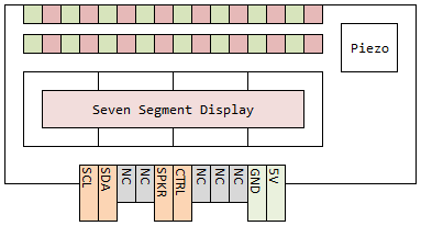
The “NC” labeled pins are “not connected” on the PCB. Those positions are only there so that they can be used to provide mechanical stability, if necessary, when connecting the display to a breadboard or perfboard.
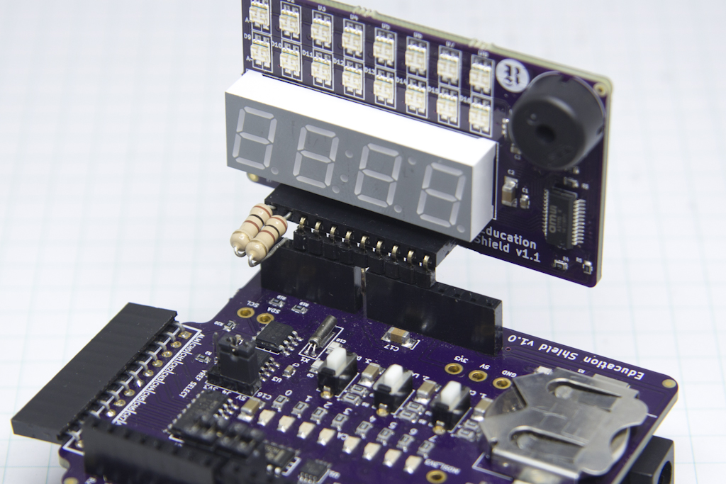
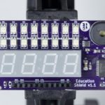
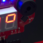
Visual Guide
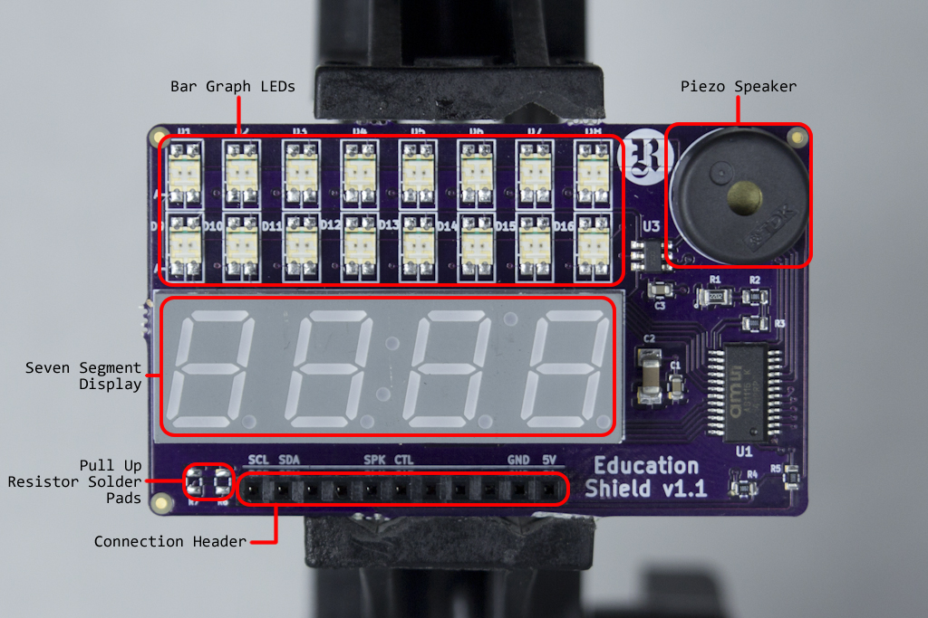
Subsystem Description
Display Driver
The heart of the I2C Display is the AS1115 LED driver chip manufactured by Austrian Microsystems. It controls the output of all the segments of the display through the use of I2C communications through the connection header. The board is designed to allow the AS1115 to manage the forward voltage requirements and maximum current driven to any portion of the display.
The I2C bus on the Display does not have pull up resistors soldered to it, however the R6 and R7 pads are available for use with 0603 sized SMD resistors. It is highly recommended that you use correctly sized external pull up resistors rather than the internal pull up resistors associated with most microcontroller GPIO pins.
Seven Segment Display
The four digit, seven segment display is connected to the AS1115 on the PCB directly. The display is a common cathode configuration featuring four discrete digits, associated decimal place LEDs and three additional LEDs that arranged as the colon delimiter in a clock display, with the third LED existing for reasons that are beyond me, but it’s there if you want to use it. The three additional LEDs are designated as L1, L2, and L3 in the datasheet and are connected to the AS1115 via the multiplexing arrangement described below.
The digits of the display are connected to the AS115 as digits 0, 1, 2 and 3, from left to right and L1/L2/Le as digit 4 via the multiplexer.
LED Bar Graph
The LED Bar Graph consists of two rows of eight red/green LEDs. The LEDs can be turned on individually or in groups with both colors being used simultaneously if desired.
The top green row is connected to the AS115 as digit 7.
The top red row is connected to the AS115 as digit 6.
The bottom green row is connected to the AS115 as digit 5.
The bottom red row is connected to the AS115 as digit 4 via the multiplexer.
Multiplexer
The multiplexer consists of a solid state SPDT switch that allows either the common cathode of L1/L2/L3 or the common cathode of the bottom row red LEDs to sink current to ground. By driving the the CTL pin low, you enable L1/L2/L3, by driving the CTL pin high you enable the bottom row red LEDs. By sending a PWM signal you can allow the display of both simultaneously, however they would necessarily both wind up displaying the same output configuration.
Piezo Speaker
A Piezo speaker is available to use as a buzzer or simple tone player in the upper right hand corner of the display. It is controlled through the SPKR pin on the connection header.
Connection
The connection of the display is designed for use with either jumper wire or right angled pin headers to allow the board to be connected to a breadboard or perfboard for soldering. The Display is designed to mate directly with any Arduino UNO or UNO compatible shield, by using a right angle connector and matching the 5V and GND pins.
The AS1115 is very susceptible to signal reflections and ringing, so if you experience errors and glitches with the display, they can most often be cured by including 1/4W 100Ω resistors in series with the SCL and SDA connections (1/4 resistors fit more securely in the socket of the connection header than 1/8W). These resistors are NOT pull up resistors, rather they are series resistors designed to reduce interference at the slave end of an I2C bus connection.