Welcome to the Rheingold Heavy, I2C and SPI Education Shield. This circuit board is designed to work with the Education Shield Tutorials as a complete education system focused on teaching the fundamentals of I2C and SPI serial communication.
Objectives
- Understand the various operating characteristics of the I2C and SPI Education Shield.
- Identify the different subsystems on the board.
- Identify the jumpers on the board and their uses.
- Understand how to connect the shield to your Arduino Uno.
- Locate the tutorials associated with each subsystem.
Background
I2C and SPI Education Shield Product Page
Texas Instruments 74HC595 Datasheet
Atmel AT30TS750A Datasheet
Microchip MCP7940 RTC Datasheet
Microchip MCP3008 Datasheet
Adesto AT25SF081 Datasheet
Setup
There is no setup required for this module.
I2C and SPI Education Shield Operating Characteristics
The I2C and SPI Education Shield is designed to be used with Arduino UNO R3 compatible boards. Use with other Arduino devices (Yun, Mega, Due, etc) has not been tested and is not supported. In most cases, the boards are NOT pin compatible. Attempting to join the I2C and SPI Education Shield with non-UNO devices may result in damage to both the Education Shield and the other board.
| Min | Typ | Max | Unit | |
|---|---|---|---|---|
| Operating Voltage - Shift Register | 5.00 | V | ||
| Operating Voltage - AT30TS750A | 5.00 | V | ||
| Operating Voltage - MCP7940 | 5.00 | V | ||
| Operating Voltage - MCP3008 | 5.00 | V | ||
| Operating Voltage - AT25SF081 | 3.3 | V | ||
| MCP7940 CR2032 Battery Backup | 3.00 | V | ||
| Vref 1 - MCP3008 | 5.00 | V | ||
| Vref 2 - MCP3008 | 3.30 | V | ||
| Current Draw - Power Up No Code | 1.50 | mA | ||
| Current Draw - LED | 18.00 | mA | ||
| Current Draw - 74HC595* | 80.00 | µA | ||
| Current Draw - AT30TS750A* | 0.0006 | 0.23 | 2.00 | mA |
| Current Draw - MCP7940* | 1.20 | 400.00 | µA | |
| Current Draw - MCP7940 Battery* | 925.00 | 1200.00 | nA | |
| Current Draw - MCP3008* | 425.00 | 550.00 | µA | |
| Current Draw - AT25SF081* | 0.002 | 0.013 | 16.00 | mA |
| Clock Frequency 74HC595* | 25 | MHz | ||
| Clock Frequency I2C | 100 | 400 | kHz | |
| Clock Frequency SPI - MCP3008 | 3.6 | MHz | ||
| Clock Frequency SPI - AT25SF081 | 8.0 | MHz |
*Values published in respective manufacturer’s datasheet.
Pin Out
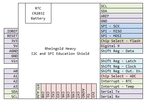
Visual Guide
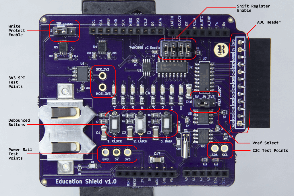
Subsystem Description
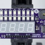
Manual Shift Register Control
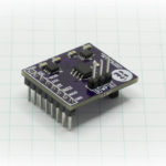
The Manual Shift Register Control consists of a Texas Instruments 74HC595 Shift Register connected to both Arduino GPIO pins through the 74HC595 Enable jumpers as well as to the Clock, Latch and Data buttons on the face of the Education Shield.
Debounced Buttons
The debounced buttons are available to be used as digital inputs by connecting the 74HC595 Enable jumpers, and driving the OE pin high to disable the shift register outputs. Button presses can then be sampled on the following GPIO pins: Clock Button = 6, Latch Button = 7, Data Button = 8.
Temperature Sensor
The temperature sensor is an Atmel AT75TS750A that communicates via I2C. The Alarm Interrupt pin is tied to Arduino Digital 2 allowing ISRs to be triggered by int.0.
Real Time Clock
The Real Time Clock is a Microchip MCP7940 that communicates via I2C. The Multifunction Pin is tied to Arduino Digital 3 allowing ISRs to be triggered by int.1, as well as utilizing the various square wave outputs and GPIO features of the pin. The Multifunction Pin is also broken out to the left most input on the ADC header.
Analog-to-Digital Converter
The Analog-to-Digital Converter (ADC) is a Microchip MCP3008 10-bit ADC that communicates via SPI. The input channels are broken out to the ADC header along the edge of the board and 5V, 3V3 and AGND are made available at that header for use in powering sensors for single ended channel measurements. Voltage Reference levels of either 5V or 3V3 are selected using the VREF jumper.
Flash Memory
The Flash Memory is provided through the Adesto Technologies AT25SF081 8-Mbit Flash Memory IC that communicates via SPI. The Write Protect pin is broken out to the WP jumper. The HOLD pin is tied directly to 3V3 so is not available for use, therefore Dual and Quad Read modes are not supported.
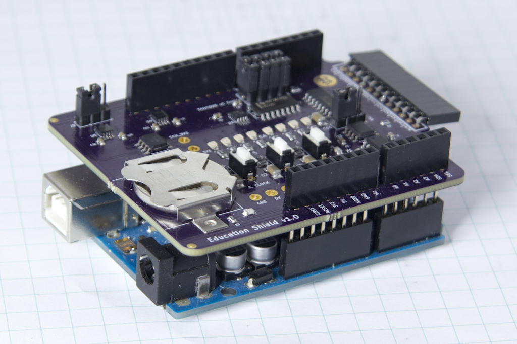
Connection
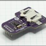
The I2C and SPI Education Shield has an Arduino UNO compatible header footprint. The long pins underneath the board are intended to be joined directly with the female pin headers on the face of the UNO. The shield can only be assembled with the UNO in one direction, with the battery holder over the Arduino’s USB and 9V power connector.
Education Modules
The tutorials associated with the I2C and SPI Education Shield are grouped together in the “Education Shield Tutorials” section of the Rheingold Heavy website.
The education modules are designed and arranged in a hierarchical manner, with each higher numbered tutorial building on knowledge gained in the previous tutorials, however, experienced users will most likely be able to jump into individual subjects directly.