Datasheets are the Rosetta Stone for your electronics projects, and unless you happen to understand the electronic equivalent of Greek, Demotic or Egyptian, they can be about as comprehensible. Without them, you won’t ever be able to pry the functionality you want out of your component, but opening up a 46 page hardcore technical document can be extremely daunting. This module will cover how I approach dealing with datasheets from the I2C and SPI component perspective. Datasheets for opamps, AFEs, microcontrollers, and their like, are their own special breed of hell.
Objectives
- Figure out how to approach reading a datasheet
- Learning how to isolate and break down the information you need
- Learn what a register map is
- Figuring out how to document the documentation
- Reasons for printing or not printing
Background
Atmel AT30TS750A Datasheet
Schematic
No schematic is associated with this module.
Setup
There is no setup required for this module.
What is a Manufacturer’s Datasheet
If you’re relatively new to electronics projects, and have only been fiddling around in tutorials, then you may not have actually ever looked at a datasheet before. That’s really cool, because if you didn’t realize it, every little chunk of electronics that’s around you right now, from the craziest microcontroller to the teeniest little stupid resistor, is fully documented through the manufacturer’s datasheet. Now obviously there are proprietary components out there where they only publish the “need to know” stuff, but really, you’ll be amazed when you start digging into learning how each and every component works.
The design of the I2C and SPI Education Shield uses 32 different parts, each of which has a datasheet that had to be reviewed. Of those 32 parts, most likely twice as many other parts were reviewed and discarded as wrong for the project for one reason or another. The only way you can make those sorts of determinations is by carefully reviewing the datasheet against your design requirements. Is the ADC resolution selectable and if so, how granular is it? How much current is this going to draw from my Arduino’s power pin? How physically big is it? Does it have any special PCB layout guidelines? How will it react across the range of operating conditions I am intending to subject it to electrically and environmentally? Those are the sorts of answers that you can (usually) derive from the datasheet.
Now, some datasheets are good, and some datasheets are horrible … and I swear that sometimes these things get published without anyone ever looking at them (*cough* Adesto Technologies *cough*). Hopefully the strategies below will help to make these awesome documents a little more user friendly.
How To Read A Datasheet
![]()
You’re approach to reading one of these documents should be relaxed. They can seem daunting, but it’s important to remember: if you’re having trouble understanding what’s in a datasheet, that’s the fault of the author, not you. So bare that in mind, and let’s have a look at the AT30TS750A datasheet linked above in the Background section.
It’s important to know why you’re looking at the datasheet, because that dictates what sort of information you should be trying to find. I get information out of a datasheet like I’m getting something off the bottom of a swimming pool – dive in for the stuff I’m after, then get back out before it suffocates me.
If I’m considering using the part in a design, my primary concern won’t be the detail of the registers, how they’re addressed, or what chunk of data goes where, I will go into the datasheet looking for the electrical characteristics and footprint information. Using the Education Shield as an example, I wanted to put a nice, easy to use I2C component on there and I thought a temperature sensor would be a good choice as it does only one thing. I pulled up the datasheet for the AT30TS750A and looked for the supply voltage and current draw first and foremost: is it compatible with a 5V microcontroller, and how much amperage does it need to run. Provided it falls within the parameters I need, I want to know what the I2C properties of the chip are: what frequency will it run at and what is the pin capacitance for SCL and SDA.
Now this may seem obvious, but the table of contents is really, really helpful. Since we’re looking for electrical stuff, use the table of contents to see if the specs we need are explicitly highlighted.
What is the supply voltage, and what is the largest current draw with a 5V supply?
Hover to read answer
What is the maximum allowable clock frequency and what is the pin capacitance for SCL and SDA?
Hover to read answer
I’ve done all the engineering and testing to make sure it’s working on the Education Shield, so at this point, you’re only grabbing this document to gain a better understanding of how to use it once it’s in place. This is similar to the process you’d go through if you were buying a breakout board to work with a specific component. All that electrical jazz is cool, but it’s not really what you, the Education Shield user are after. You need to know how to use the chip, and that’s where the Device Communication and Device Operation sections come into play. These read like any technical manual, but at their best, tell a linear story of how to interact with the device you’re learning about.
Go ahead and read those two sections now and then come back to this point.
Welcome back. Hopefully you discovered that the Device Communication section was basically just the general specification for how I2C works. The Device Operation section contains the more important information. All the various modes of operation are listed in there: temperature measurement, one shot mode, alert pin, comparator function, etc. It hasn’t told you how you interface with it, just what you can achieve.
After you look at enough of these data sheets, you learn that the secret sauce is in the registers. That’s where the data resides to be read, that’s where data goes to be stored, that’s where configurations are set. The truth is, what you’re looking for is the register map.
The Register Map
Registers are discrete chunks of storage, usually one or two bytes in size, that hold values dealing with either the data the sensor provides, or the way the sensor operates. It is very helpful when the datasheet author provides a map, that lists all the registers and what their purpose is. In the case of the AT30TS750A, you find that map on page 14, under the section called “Registers”. It looks like this…
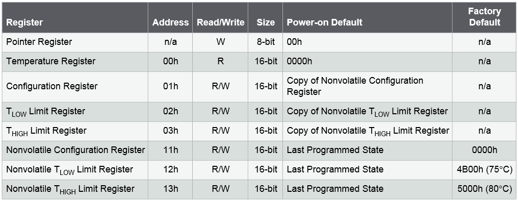
That’s actually a very nicely organized table. Some that we’ll deal with from other subsystems on the Education Shield will be far more extensive, covering pages of tables. I picked the AT30TS750A specifically because of the ease of use, and that’s directly reflected in that concise register table. The headings change from map to map and manufacturer to manufacturer, but this is a very good example of what you run across.
Register
This is the name given to the chunk of data by Atmel. Most often these have nice descriptive names so you can easily see what each register is responsible for, sometimes they have names like “Pointer Register” that will require a little more work to figure out. Generally, you’ll be looking for things like “Reason I Bought This Chip Register” and “Configuration Register”. This is a temperature sensor, so there is a “Temperature Register”, and the config register is exactly what it sounds like.
Address
This is the hex address that you will send to the device, telling it where you want to read from or write to. This is not the I2C address, but a location within the chip. If the I2C Address is Hollywood, the register address is 8901 Sunset Blvd. For SPI devices, it means exactly the same thing.
Read/Write
Exactly what it means. Can this register only be read from, only written to, or both? If you look at the example above, it makes sense that you can only read the temperature register, because you’re not setting the temperature. However, the configuration register is R/W, meaning you can do a quick scan of it to find out how it’s configured to operate and then modify it based on the logic in your code. That’s why bit masking and bit shifting are such vital skills to have… read out the current config, change a few specific bits in it leaving the rest intact, and send the new config back.
Size
This tells you how much data the register contains, and will be one of your first keys to troubleshooting something. If you’re trying to read or write to the configuration register and you’re only sending 8 bits, then chances are something is going to screw up. If you’re trying to read 24 bits of temperature data, well you’re gonna get some whacky responses.
Power-on Defaults
The power-on defaults tell you what state the register will be in when you first turn it on. In this case, the config, low and high limit registers are copies of their non-volatile versions (makes sense), and the temperature and pointer registers begin their lives zeroed out.
Factory Default
If there can be a specific value in a particular register from the factory, Atmel is listing it here.
Using The Register Information
There are any number of ways to approach how you work with the register information, including grabbing what seems like the most interesting register and blasting it at your chip to see what you get back… but I would caution you that the best approach is to first scan through the entire register chapter, then follow up by rereading the description of any configuration registers with an eye toward the details.
Once you’ve given yourself an overview with a firm grasp of the configurations, you have a good start on figuring out how to make the chip do what it’s supposed to do.
The AT30TS750A registers in this datasheet will be covered in detail in the respective modules related to that chip.
Documenting the Documentation
There is no way I can keep the register data clear in my head, even for a chip as simple to use as the AT30TS750A, so I’ve got to do something to make it more readily accessible. There are a couple ways I’ve found for doing that.
The Old Print and Highlight Method
It’s hard to go wrong with printing out your datasheet, putting a sticky tab on the important register descriptions, grabbing your highlighter and going to town on it. This was my preferred method, back when I had access to laser printers that spat out 25ppm B&W, using toner I didn’t have to pay for.
I really do like not having to look up at the screen sometimes when I’m thinking, and being able to walk out of my lab and still have the reference material obviously holds benefits.
However… I don’t have access to a laser printer anymore and the cost of inkjet cartridges is coming out of the Rheingold Heavy budget.
The Outline
This is my new preferred method of documenting the documentation – how I take notes on a data sheet. I create an outline, describing the registers in plain(er) English, with a reference at the top showing which page in the original PDF holds the register map, and what the URL for the datasheet is. If I need to take a table or graph out, I copy and paste it into the document, but generally, it’s an outline of the registers translated from Manufacturer into Dan.
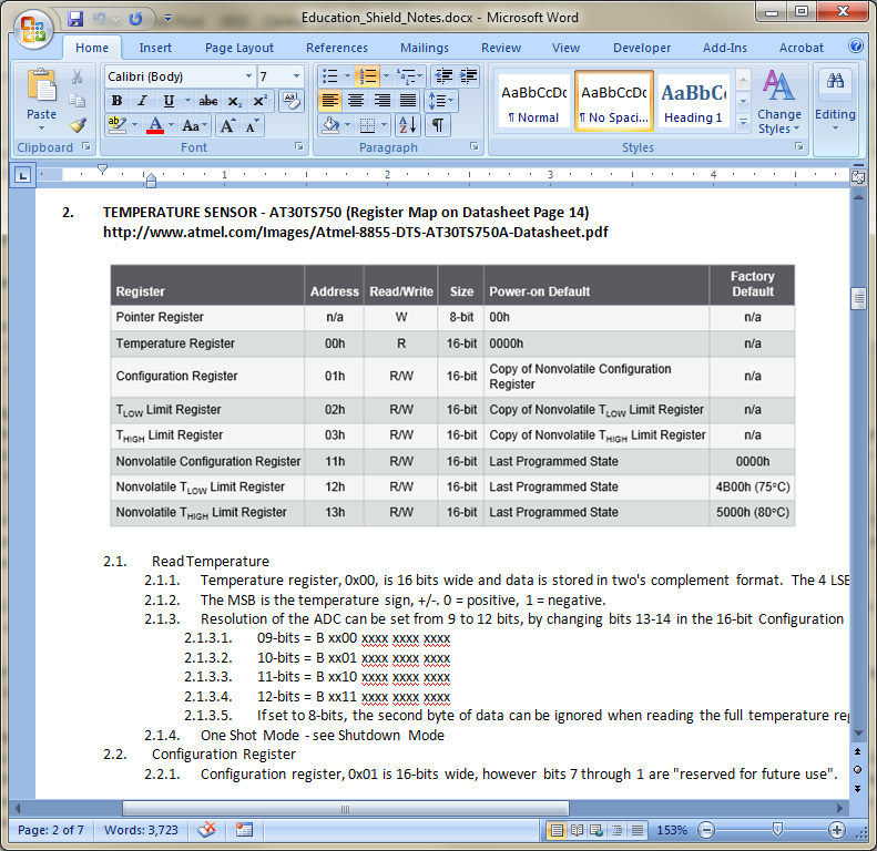
Then, when I go to print out the details I need to have on hand when I code, I only wind up with two or three pages of condensed information that’s exactly specific to the task at hand, rather than a 48 page tome. If I’m at the point of writing code, hopefully the pin capacitance isn’t really important anymore.
