[mathjax][/mathjax]An optoisolator is used to electrically isolate one part of a circuit from another. Say you’ve got a noisy part of a circuit, full of magnetic coils like relays or motors, stuff like that, and then you have an ADC in another part of the circuit that’s measuring some super low voltage sensor signal. You need to use the values of the ADC to change the output of the motor, but can’t risk all the voltage fuzziness of the noisy circuit interfering with the carefully laid out analog stuff. The optoisolator separates the two by using some photosensitive substance and a light source, the light source increasing or reducing the conductivity of the photosensitive substance in a predictable fashion. That way your ADC can keep reading merily along, and you can adjust the motor speed by flashing a light, rather than having a direct copper connection that could allow all those horrible inductive spikes to flow back into the rest of your circuit.
Typically, it is a combination of an LED, near infra-red I think, and either a photoresistor, phototransistor or some other optical technology I’m really not familiar with. As you’d expect, the opto-isolator page at Wikipedia is a great place for info. On Digi-Key, the cheapest one available is a combination LED / Phototransistor from Lite-On that costs $0.37 in single quantities. I’m going to make one with a light dependent resistor (LDR), a white LED, a paper towel roll, and some tinfoil – a DIY Optoisolator!
Why? Why the hell not?
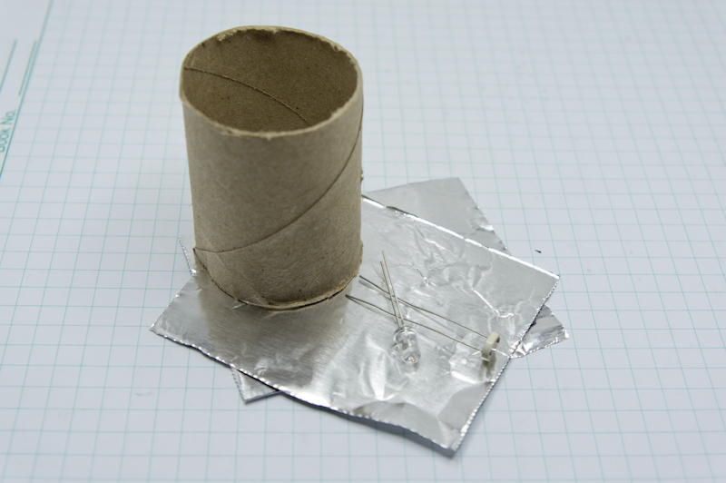
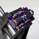
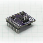
Really, it’s pretty simple… poke two pairs of holes opposite each other into the sides of the cardboard tube, with the holes narrow enough to allow the leads of the LDR and the LED to pass through to the outside easily. Then do just that… LDR on one side, LED on the other and bend the pins down the side so that the components are generally facing each other inside. Then use a couple of squares of tinfoil to seal up the ends. There is a hazard of creating a short circuit by using tinfoil, if the leads touch them, but it was the quickest solution I could come up with for closing the ends opaquely and still make the cover easy to take off and see inside. I just used a fingernail to crumple and bunch the edges of the foil downwards by putting the tube on end and nudging the stuff down. A little bit of scotch tape over where the leads exit the tube probably couldn’t hurt either to keep things in place.
[masterslider id=12]
You’ll want to connect the LED to a PWM pin on your Arduino, I used pin 3, and the LDR to an analog pin, I used pin 0. Current limiting resistors on both are necessary. On the schematic I’m using a 100Ω resistor for the LED, because it’s a “pure white” color, and has a relatively high forward voltage of 3.2V at 20mA. I rounded the result up to 100Ω. Using other LEDs of other colors will be different so make sure you consult the datasheet and do the math too.
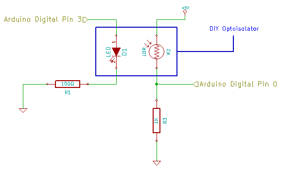
To maintain consistency with the measurement methods used on the Measuring Light Dependent Resistors page, make sure that you connect 5V to the LDR and the LDR to the series resistor, rather than the other way around. They both work, but we want to measure the voltage drop across the series resistor… just because.
What we’re going to do, is send varying PWM signals to the LED, and measure how much voltage the LDR allows to flow at those various PWM levels. I really have no idea what to expect for results, other than a decrease in resistance as the PWM level increases… higher PWM means more light, and more light means less resistance. There is the possibility that the LDR can adjust it’s resistance level so fast, that it will actually fluctuate with the PWM duty cycle, but I am hoping that’s not the case… the datasheet for my LDR is sort of lacking in specifics.
In the loop() section of the code, you set the PWM level directly, upload the sketch to the Arduino, then open the serial monitor and watch the results spew forth. It takes a second for the value to stabilize. This is a very manual way of doing it, but it was quick to put together.
|
1 2 3 4 5 6 7 8 9 10 11 12 13 14 15 16 17 18 19 20 21 22 23 24 25 26 27 28 29 30 31 32 33 34 35 36 37 38 39 40 41 42 43 44 45 46 47 48 49 50 51 52 |
/* A sketch that controls the output of an LED that is encased inside a sealed chamber with a photoresistor. This utilizes the ADC Smoothing algorithm from the Arduino website: http://arduino.cc/en/pmwiki.php?n=Tutorial/Smoothing Thanks to @mrdawilson for the efficiency improvement when creating the array! https://rheingoldheavy.com/diy-optoisolator/ */ // Setup our pins const int ledPin = 3; const int ldrPin = 0; const int numReadings = 25; // Setup our variables int readings[numReadings] = {0}; // Holds the values from Analog 0, initialized to zero. int index = 0; // Holds the current index of the array int total = 0; // Running total of the value of the array int average = 0; // The average to be computed later void setup() { // Setup our pins as necessary pinMode (ledPin, OUTPUT); pinMode (ldrPin, INPUT); Serial.begin (9600); } void loop() { int pwmLevel = 128; // SET YOUR PWM LEVEL HERE analogWrite (ledPin, pwmLevel); // Set the LED output in the optoisolator total = total - readings[index]; // Remove the previous reading from the running total readings[index] = analogRead(ldrPin); // Read from Analog 0 total = total + readings[index]; // Add the latest reading to the running total index = index + 1; // Advance to the next position in the array if (index >= numReadings) index = 0; // If we reach the end of the array, set the index to 0 average = total / numReadings; // Calculate the average values. Serial.print (pwmLevel); Serial.print (","); Serial.println (average); delay (1); // Delay 1ms to stablize } |
I hooked it all up and ran through a set of PWM values: 0, 1, 2, 4, 8, 16, 32, 64, 128, 255 and recorded the reading of Analog 0.
| PWM Level: | 1 | 2 | 4 | 8 | 16 | 32 | 64 | 128 | 255 |
| analogRead: | 19 | 41 | 78 | 135 | 220 | 322 | 433 | 555 | 665 |
The reason for selecting the exponential increase for the PWM value was because I figured I didn’t want to sit here all day measuring each step along the way, and I strongly suspected that there would more action lower down than higher up.
Time for a bit of math. I want to know what the resistance of the LDR in ohms is for each PWM level. Let’s figure out what we know…
- The reading on Analog 0, is the voltage drop across the series resistor R1, which I measured with a multimeter as 987Ω.
- The Arduino ADC is 10-bit, meaning 1024 different levels, with a 5V reference.
- Using the value of the resistor, and the voltage across it, we can use ohm’s law to determine the current, Icircuit.
- The current draw in a series circuit is constant at all points, so we can use the current to determine the total resistance in the circuit, knowing that the input voltage is 4.87V measured with a multimeter.
- We can subtract the value of the series resistor from the value of the total resistance to find out the resistance of the LDR!
Each step works out to…
\[\begin{aligned}
\small V_{measured} & = Analog_{0} * \frac{V_{ref}}{1024}\\
\small I_{circuit} & = \frac{V_{measured}}{R_{1}}\\
\small LDR\Omega & = \left(\frac{V_{in}}{I_{circuit}}\right)-R1
\end{aligned}\]
So taking the PWM Level of 16, we can substitute things in as follows…
\[\begin{aligned}
\small 220 * \frac{5.00V}{1024} & = 1.07V\\
\small \frac{1.07V}{987\Omega} &= 0.00109A = 1.09mA\\
\small \left(\frac{4.87V}{1.09mA}\right)-987\Omega & = 3488\Omega
\end{aligned}\]
Run it against the entire table (preferably using some spreadsheet automation), and you can see the value of the LDR at each PWM level…
| PWM Level: | 1 | 2 | 4 | 8 | 16 | 32 | 64 | 128 | 255 |
| analogRead: | 50824 | 23023 | 11634 | 6305 | 3488 | 2070 | 1286 | 787 | 493 |
I’d say we’re able to affect a pretty dramatic change inside our cardboard tube!
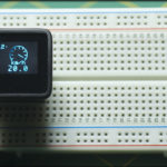
Now, while I’ve been sitting here, typing this in, formatting LaTeX equations and writing HTML tables, I also had a little sketch running in the background, taking the average of 10 samples for each PWM level and doing that 100 times per level. Once I sorted and swizzled the data, here is the chart that resulted…
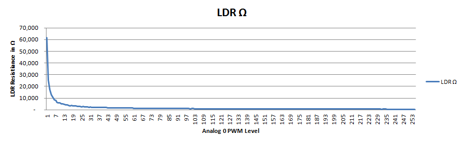
As I suspected, the majority of the action is happening to the left side of the curve with a drop in resistance from, well, something really big, to 61K when you first turn the LED on at PWM 1, then 25K, 17K, 12K and 10K for 2, 3, 4 and 5. So, no, it’s not subtle… but this isn’t exactly high end engineering either 🙂
Out of curiosity, I was wondering what the difference would be if I used a different type of LED, like a typical red LED that I have in stupidly large quantities just laying around. Here’s what I got when I switched to the red LED with a 330Ω current limiting resistor because it has a much lower Vforward.
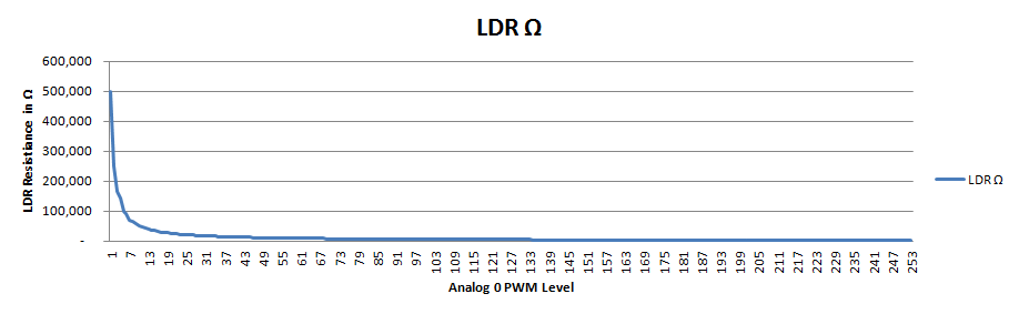
First thing… whoa! It didn’t even budge the LDR until PWM level 3 and then its at 500KΩ. That’s pretty massive. But while the numbers are larger, the curve it generates seems pretty consistent. I have zero skill with statistics, but my eyeballs tell me they look similar.
I checked the datasheets for both the white and the red LED, and unsurprisingly, the amount of “luminous intensity”, something that I take to mean the brightness that your eye would perceive, is way different: 5000mcd @ 20mA for the white LED versus 200mcd @ 20mA for the red LED. So, again unsurprisingly, the red LED starts off, and maintains, higher resistance in the LDR, because the intensity of the light is substantially less.
I checked Digi-Key, and they stock a red LED from Würth Elektronik that outputs 5000mcd at 20mA, 35 cents in single quantities. I might buy me some of those and try them out. That would show the difference in resistance based on the wavelength of the light with no difference in light intensity… 480nm white wavelength vs. 623nm red wavelength.
I wonder if you can use this bodgy DIY optoisolator to actually control something, like a motor?