A list of possible design revisions for subsequent I2C and SPI Shield boards…
- Done 18-AUG-2014
Rev: Move the temp sensor from being located over the ATmega328 - Done 18-AUG-2014
Rev: Spread the LEDs out a bit. - Done 18-AUG-2014
Rev: Move all bottom side components top side so small batch assembly houses can build it. - Done 19-AUG-2014
Rev: Connect the buttons to available pins so that they can be used long term as well. Three hardware-debounced buttons would be valuable. - Done 19-AUG-2014
Rev: Make the 74HC595 available in all sketches so that bitwise operations can be visualized on the LED array. - Done 18-AUG-2014
Rev: Modify battery backup circuit for the MCP7940N to match the appnote. - Done 19-AUG-2014
Fix: Increase the pad size for the SOIC16 footprint, see if the SOIC8 is a good guide. - Done 18-AUG-2014
Fix: Add test points / pads / header - Done 19-AUG-2014
Fix: Change MCP3008 bypass cap to 1uF, as per datasheet. - Done 18-AUG-2014
Rev: Move the VREF silk screen so its more visible. - Rejected
Rev: Consider putting an LDR or pot on the board with a jumper to give something to measure with the ADC out of the box - Done 18-AUG-2014
Fix: Change signal at the U4 level shifter, currently MOSI and SCLK are mixed – A1 -> B2 A2 -> B1. - Done 08-NOV-2014
Rev: Change the GND pad for the battery holder to a larger physical space to ensure good contact with the battery. - Rejected
Rev: Remove Test Points. - Done 08-NOV-2014
Rev: Remove 0Ω jumper resistors. - Done 09-NOV-2014
Rev: Add a pullup resistor for the Temperature Sensor Alarm pin. - Done 09-NOV-2014
Rev: Add a jumper to allow control of the shift register OE pin. - Done 09-NOV-2014
Rev: Add 10uF cap at +5V
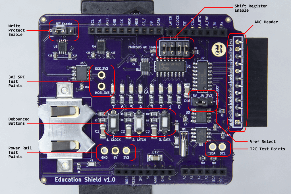
After including the necessary design revisions, this is the final production version for the I2C and SPI Education Shield v1.