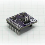
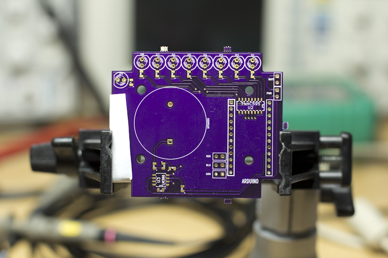
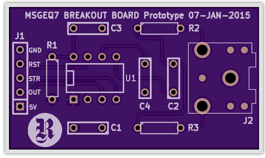
I’m in the process of creating an MSGEQ7 Breakout Board, for my “Abandoned Kickstarter Recovery” project, and when I went looking for a component to use for the 3.5mm stereo jack, I found one that had both electrically relevant pins (tip, ring and sleeve), but also needed four mechanical, non-plated through holes drilled in order to provide mechanical stability during insertion and removal of a stereo plug. After plotting your gerbers and generating drill files, you wind up creating two .drl files: a plated and a non-plated. Unfortunately, when you upload these to everyone’s favorite PCB prototyping service, OSH Park, you get boards that won’t work, even though you won’t actually have an error pop up. Unless you know to look for the problem, and it isn’t obvious, you would wait patiently for the boards to arrive and discover that only the non-plated holes were drilled. What you need to do is combine your KiCad drill files into one.
The Two Drill File Problem
This isn’t the first time I’ve run into this. In fact, I was building a toy for a friend’s son and the boards came back with only the mechanical holes drilled, but not a single PTH, even though I thought I had submitted it correctly! I resolved that issue quickly with OSH Park support and was able to submit a replacement job. And just so we’re clear on nomenclature… PTH = “Plated Through Hole” which is the sort of thing you’d stick an old school resistor through and solder in place but also is what comprises a via, and NPTH means “Non-Plated Through Hole”, also sometime referred to as a “mechanical”, which is a simple hole drilled through your PCB at the fabricator, the sort of thing you’d put a screw through into a stand off or something like that.
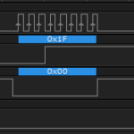
The problem between the top board and the bottom board above, is that in the top board, two drill files are created, and in the bottom board, those files have been combined into one. You can see that the mechanical holes appear in both, but only in the bottom do the PTH drills exist.
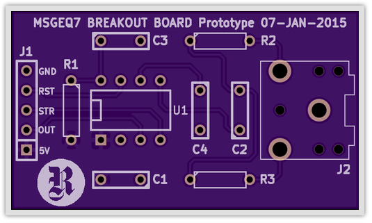
I’ll use the example of the MSGEQ7 Breakout Board. When I enter KiCad and use the Plot feature to generate my gerbers and drill file, the end result looks like this…
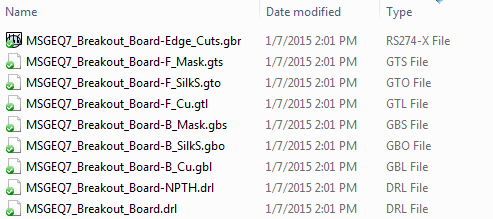
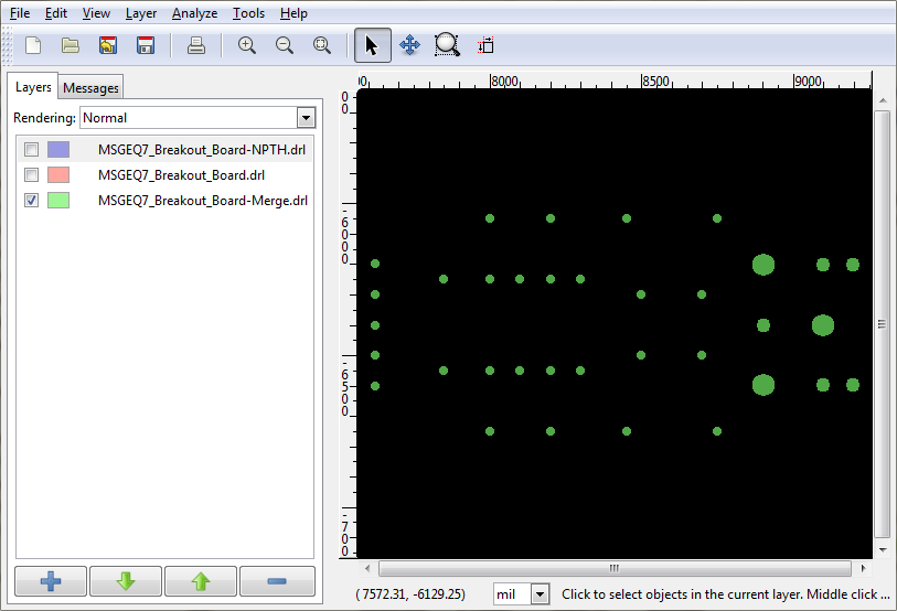
At the bottom of the list, you see MSGEQ7_Breakout_Board-NPTH.drl and MSGEQ7_Breakout_Board.drl. The NPTH unsurprisingly contains the NPTH drill specifications, and the regular .drl file contains all the PTH and Via drill information. If you look at the two boards above carefully, you’ll see that not a single one of the vias was drilled through on the top board! They look like teeny surface mount pads.
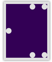
As always, I do a gerber check of the file using GERBV and this is what the top copper and drill files look like. The arrows point to the mechanical, non-plated, through holes, which will be significant.
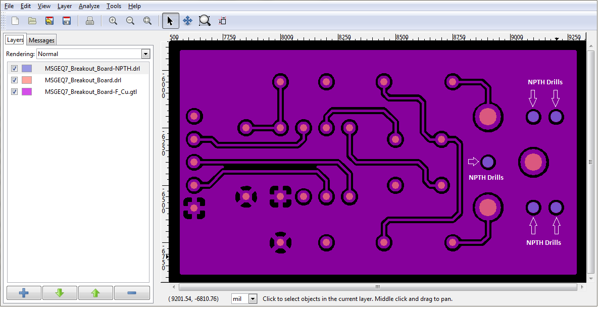
You have to sort of sit there and understand the color coding and how they mix colors to really see what’s happening in that screen capture. Being able to click on the check marks on/off/on/off and see them change is also very helpful, but what you’re seeing is that the big purple plane has circular holes drilled into it all over the place, and the orangish ones will receive copper plating, while the dark purple ones will not. Additionally, you can see that the dark purple, NPTH, drills, don’t have copper annular rings around them to solder to. They should just look like holes drilled through the board ultimately.
The problem will occur when you take that list of files up there, zip them up and bring it to OSH Park. This is what you’ll see for your previews…
Looks snazzy doesn’t it? Except that there is a really big issue in there. If you compare that with the drills as they looked in our GERBV view, you don’t see holes drilled in the NPTH positions, you see copper pads! Additionally, when you scroll down a bit, and look at their rendering of the drill file, it looks all kinds of kooky…
The reason this has occurred is because OSH Park only processes one drill file, and in this case, for some reason, it processes the normal .drl file when it first renders the board, and then it processes the NPTH drill file when it renders the drill view.
The solution to this, is to combine the two drill files into one so that OSH Park gets all the information it needs from the single merged drill file.
Combining KiCad Drill Files
Click here to download the GERBV tool necessary to merge drill files.
Once you have GERBV installed, the process is fairly simple. First, use the interface to load up your two drill files, using FILE -> OPEN LAYERS.
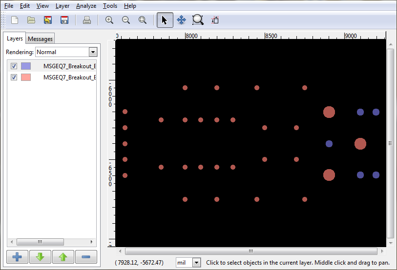
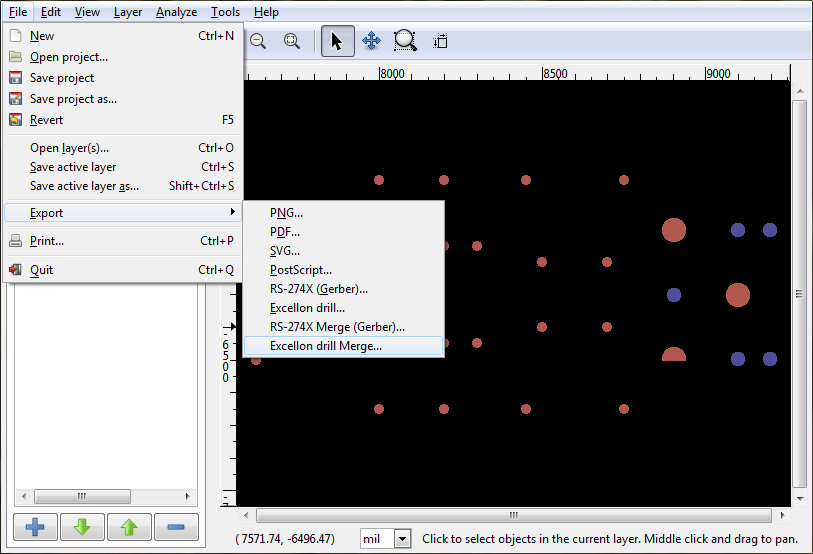
With your two layers now loaded up, you can see the different colors in the interface for the PTH and the NPTH drills. We’ll now fix that. Click on FILE -> EXPORT -> EXCELLON DRILL MERGE.
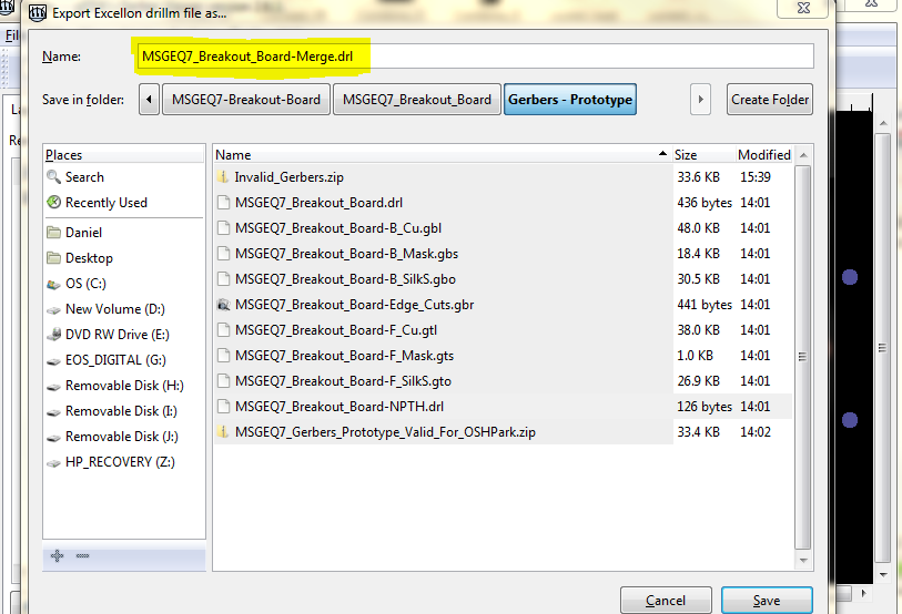
In the interface that opens up, select a new name for your merged drill file. I like to give mine a very clever and unique name like “PROJECT_MERGE.DRL”, because I am unimaginative.
When it has finished processing your drill files (and it shouldn’t take long at all… think seconds instead of minutes), you’ll get a message saying something like “Merged visible drill files”. Note that the display is a little wonky in that screen capture because of the swap over to the message tab.
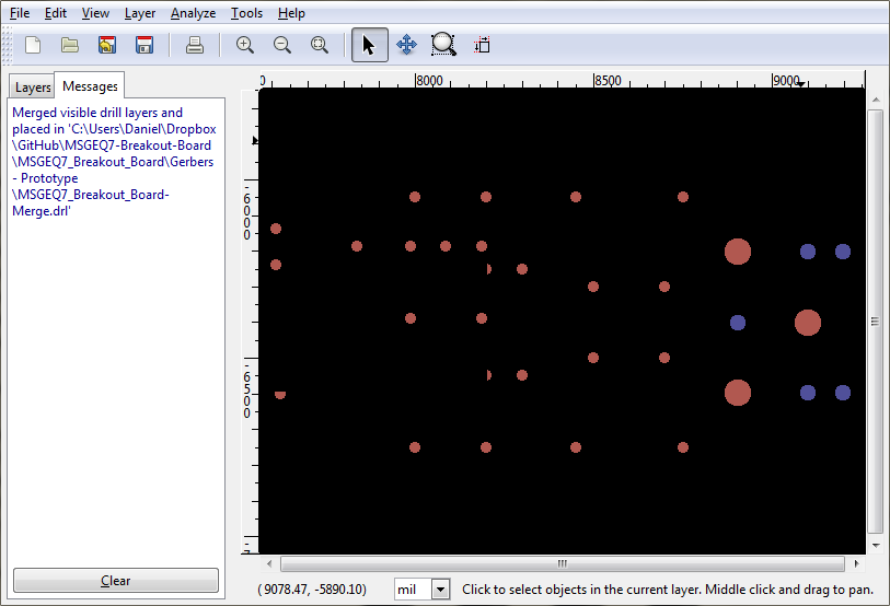
As a quick test, I like to load up the merged drill file into GERBV and compare it with the two files already loaded, so I can make sure that all bases are covered. In this image, you can see that all the drill positions we expect are now a uniform color that matches the color of the merged drill file.
Final Test – Bringing It Back To OSH Park
When you have this completed, create a new zip file to upload to OSH Park, but make sure that you only put the merged drill file in it and leave the two original drill files out. With the new zip file, this is what the preview looks like…
You can see that the NPTH drills are now a lovely inky black, showing that they will be drilled through along with everything else. And the final proof is in the render of the drill file itself…
… which now shows all the drill positions, plated and non. The processing algorithm either at OSH Park or at their fabrication partner knows that if the drill has no copper trace running to it, and no annular ring, then it doesn’t need to be plated from one side to the other with copper.