In Part 8, we covered all the different subcircuits surrounding the ATMEGA16U2 microcontroller, with the exception of the 16MHz Crystal Oscillator (XTAL) and supporting components. This section fills in that gap and completes the 16U2 subsystem.
Build An Arduino UNO R3 from Scratch Table of Contents
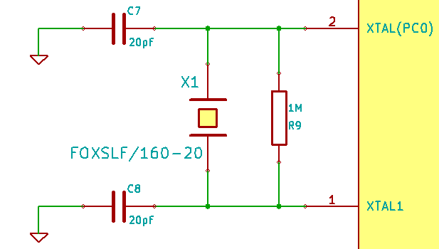
The 16Mhz Crystal Oscillator Official Schematic
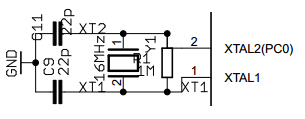
The xtal acts as the ridiculously fast metronome for your microcontroller. This little piece of quartz bangs away 16 million times a second, and does it with pretty good accuracy. Unfortunately, the official schematic doesn’t list any manufacturer information for it! Only “16Mhz”. So we have to do some digging to understand how to select this part correctly. I leaned heavily on the Crystal Oscillator Basics Appnote from Microchip in explaining many of the following specs to me. It’s also impossible to figure this out without having the Atmel ATMEGA16U2 Datasheet to reference.
First off, the datasheet says we can use either a crystal oscillator or a ceramic resonator. Looking around, I couldn’t find a resonator that had the accuracy I wanted (30ppm or less hopefully), so a crystal oscillator (xtal) was the right solution. But which one? A search for 16Mhz Crystals on parts.io netted 104,000 search results!
Frequency
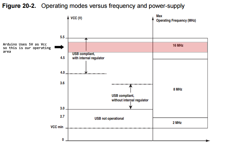
How fast does it need to be? The datasheet (table 8-3 page 30) says any oscillator from 400kHz to 16Mhz is valid. However, the faster your oscillator runs, the more power you’re likely to consume. Now, since power isn’t really an issue for us (ok, it could be if you’re running off a battery), we could just say, “Hell, let’s go all the way to 16Mhz! WOOT!”. We do have a minimum speed imposed on us by a very application specific reason: because we are doing USB signalling, we have to use an 8Mhz crystal at a minimum. The technical reason why 16Mhz was chosen as the operating speed is unclear to me, as the only thing the 16U2 micro does is USB/Serial conversion, which could easily be fulfilled at 8Mhz. We are using the internal USB voltage regulator, meaning our VCC has a minimum of 4.0V, and use of a 16Mhz crystal is allowed at 4.5V VCC, so it may have been a case of “well, we’re going with 5V VCC across the board, so we may as well give ourselves the extra speed”. Alternatively, it might have been forward planning, allowing greater use of the 16U2 in the future. Ultimately, it could have been a case of “hey, we got a really good deal on this 16Mhz crystals.” too.
Ok, so we’re going with a 16Mhz Crystal Oscillator. Looking that up on parts.io you see a bewildering set of possible selection criteria, none of which are covered in the datasheet.
Fundamental or Overtone
The faster your crystal hummmms, you eventually reach a point where it can’t hum any faster, at that point you don’t use the actual frequency it generates (the fundamental frequency), rather you use an overtone on top of that. An overtone is like the high pitch you hear when you pluck a guitar string. Sure you hear the E or the G or the D, etc, but particularly as the volume dies down, you can hear the overtone, many octaves above the original sound. This is how you can use an oscillator at a frequency higher than it’s fundamental frequency. Fortunately for us, that’s really all RF sort of stuff, and we can just use a Fundamental Frequency Crystal Oscillator without worrying about needing the 3rd, 5th, 7th or 9th overtone.
Series vs. Parallel Resonance
I’ll be honest, I don’t fully understand the concepts of series and parallel resonance beyond the basic theory, and the more I dig into it, I find a chicken vs. egg problem: most appnotes and websites copy/paste the same phrase, “Series resonant crystals are intended for use in circuits which contain no reactive components in the oscillator feedback loop. Parallel resonant crystals are intended for use in circuits which contain reactive components usually capacitors) in the oscillator feedback loop.” Except, you wouldn’t have capacitors in the circuit unless it was parallel in the first place, because a series resonant crystal is only effective if there are no capacitors. And yet, they also all refer to being able to pull the clock using load caps, even when using series resonant crystals.
The Wikipedia entry on Crystal Oscillator Resonance Modes says that series resonance is typically used with crystals above 30Mhz.
So let’s use some sideways logic to help make a decision…
- Every crystal circuit design I’ve ever done looks exactly like this one does, and they’ve always been parallel.
- There are about twice as many parallel crystals in inventory at distributors than there are series crystals.
- The part popularity index at parts.io shows that the top 10 16Mhz crystals being purchased are all parallel.
I admit, this is a crappy way to make an engineering decision, but it is what it is. Let’s just go with parallel, and worry about series resonators when we start building radar systems or some crap like that.
Frequency Tolerance
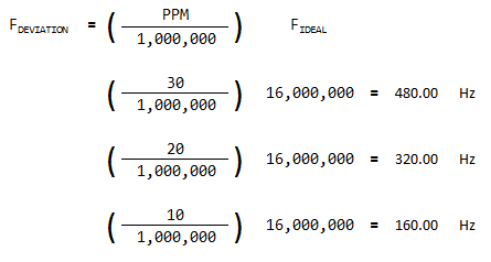
Frequency tolerance (as sort of mentioned above) is measured in Parts Per Million (PPM). This is easier to understand if we talk about the 32.768kHz crystal used with Real Time Clocks. Ideally, the crystal will go dingaling 32,768 times every second, or thought of another way, the clock IC interprets a single second as having occurred every 32,768 dingalings. If your crystal deviates by some value “x” PPM either way, then you’ll have either too many dingalings in one second, meaning that your clock is running fast because it got to 32,768 dingalings faster than the ideal one would, or too few dingalings in one second, meaning your clock is running slow because it took too long to get to a full dingaling count.
You can read all the calculations needed in the Real Time Clock link above, but that’s what PPM means… the greater the PPM value, the conceivably slower or faster your oscillator is running. You want that number as low as possible, with lower values meaning higher component price. Typical values are 10, 20 or 30ppm. Above 30 is way to inaccurate, below 10 starts to get into “custom crystal” territory.
Frequency Stability and Aging
Frequency Stability and Aging are also listed in PPM and reflect the expected deviation from ideal based on either environmental factors (mechanical vibration, temperature fluctuations, etc) or the actual age of the component. As with tolerance, the lower these numbers are, the more expensive the component. We’re not doing some crazy industrial or aerospace application so I really don’t care about these values.
Load Capacitance
The load capacitance value is listed in picofarads and is the value of capacitor required to bring the crystal to its specified frequency and thus provide stable and accurate time keeping. All you have to do is buy a pair of caps with that value and you’re golden.
16MHz Crystal Choice
After swizzling all of the data points above and doing some search on parts.io, I finally selected the Fox Electronics FOXSLF/160-20e. Here is how it stacks up against the specs listed above…
| Specification | Desired Trait | FOXSLF/160-20e Spec |
|---|---|---|
| Frequency | 16MHz | 16Mhz |
| Fundamental or Overtone | Fundamental | Fundamental |
| Series or Parallel Resonance | Parallel | Parallel |
| Frequency Tolerance | Less Than 50PPM | 30PPM |
| Load Capacitance | Any Value Is Fine | 20pF |
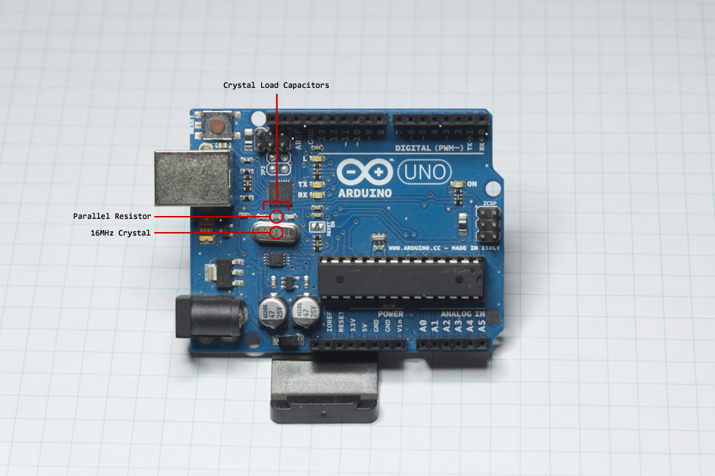
To go with this crystal, I’ve selected a pair of Kemet 20pF capacitors, C0805C200G5GACTU, with a nice tight 2% tolerance. The two capacitors and the crystal above will provide the external oscillator source for the ATMEGA16U2 on our Arduino From Scratch.
Parallel Resistor
The parallel resistor on the official schematic came out of nowhere, and I can’t find any reason for it being there. It’s not mentioned in either the xtal or 16U2 datasheet, leaving me at a loss for why it exists. I’m replacing it with a 0Ω resistor, so if it turns out to be necessary it can be added.
With a significant amount of very helpful input and coaching from Philip Freidin, who also pointed me in the direction of several crystal appnotes, I have a much better understanding of the need for this parallel resistor.
This resistor is actually acting as a feedback resistor for the micro’s internal inverter to which the crystal is connected, and biases the inverter’s input into the linear region. “Biasing into the linear region”, means that it is amplifying the crystal’s oscillation without ever fully saturating at one of the voltage rails. When power is first applied to the system, this feedback resistor helps the components that make up the oscillator circuit, both internal to the micro and the external parts we provide, to get ringing at the correct frequency faster.
One of the more valuable appnotes I read, is this one from Crystek: http://www.crystek.com/documents/appnotes/Pierce-GateIntroduction.pdf. The 1M resistor value that is listed on the official schematic is reinforced by the values stated in that appnote, so I will include it in my schematic as well.
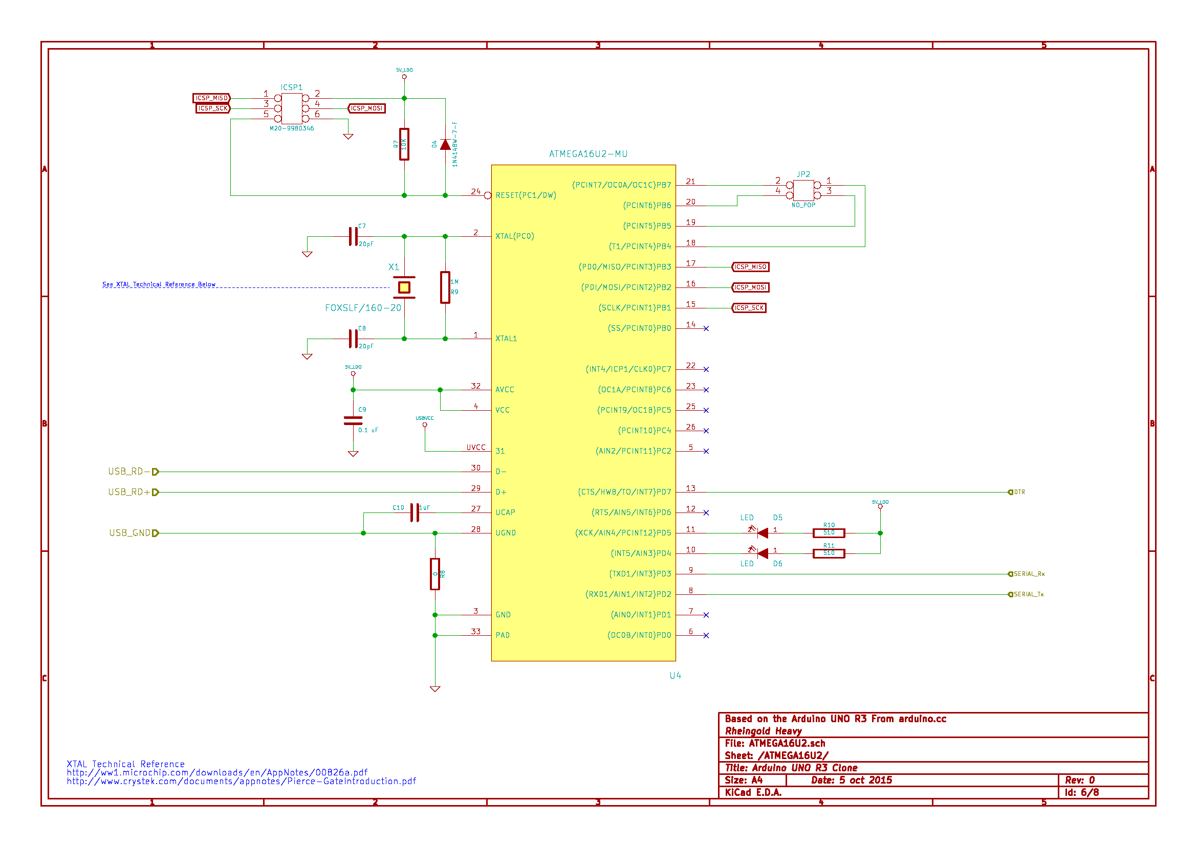
Full ATMEGA16U2 KiCad Schematic and BOM
Once again, here is the shrunken ATMEGA16U2 Subsystem, drawn in KiCad.
Here is the ATMEGA16U2 Subsystem BOM: Arduino UNO R3 From Scratch ATMEGA16U2 Subsystem BOM
In Part 10, it’s time for the big boy, the brains behind the outfit, the ATMEGA328P subsystem.
UPDATE
Here is the updated portion of the crystal circuit, highlighting the 1M resistor..