Welcome to the AT30TS750A Temperature Sensor from Atmel. This module will cover the functionality of the chip based on the datasheet.
Objectives
- Understand the various operating characteristics of the AT30TS750A.
- Understand the difference between interrupt and comparator modes.
- Understand what the fault tolerance queue is.
- Understand how the volatile and non-volatile registers interact.
- Understand the difference between RLCK and RLCKDOWN.
- Understand shutdown mode.
- Understand the General Call Reset.
Background
I2C Signaling
How To Read A Datasheet
Atmel AT30TS750A Datasheet
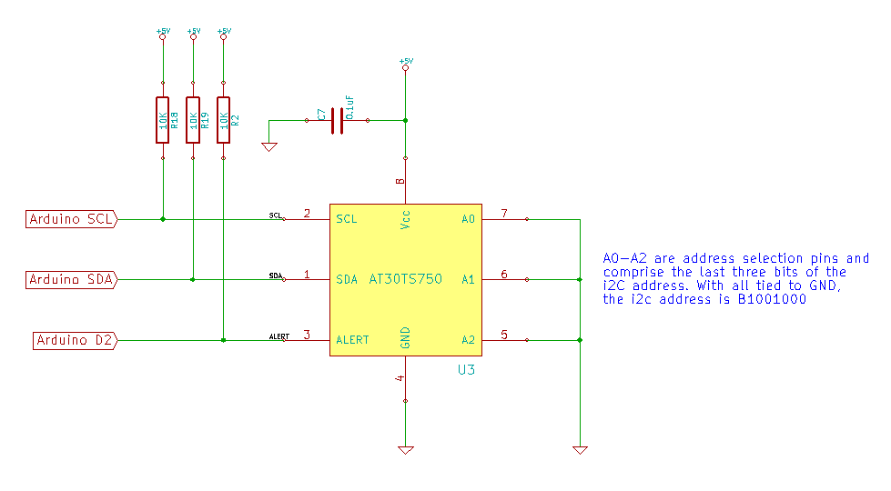
Schematic
Education Shield – AT30TS750A Temperature Sensor Subsystem
Setup
There is no setup required for this module.
AT30TS750A Functionality Overview
As is obvious by this point, the chip communicates over I2C, and is capable of up to 1000kHz speeds (Fast Mode). Our Arduino is only capable of 100kHz standard mode by default, but the chip is compatible with the slower speed. Reading through the Device Communication section of the datasheet raises no concerns about odd signaling, as everything points to 100% compliance with I2C standards: Start Conditions, Stop Conditions, ACK/NACK… all of that is in the DNA of the AT30TS750A.
From a functionality standpoint, the AT30TS750A is a temperature sensor, pure and simple. Everything it does revolves around that basic feature. It is able to measure temperatures from -55C to +125C in a variety of resolutions. However, in addition to just measuring temperature, it includes the following features…
- Configurable temperature alarms, based on high and low limits
- Non-volatile configuration registers so settings aren’t lost at power down
- The ability to lock down the configuration permanently.
- Shutdown and One Shot Mode
Temperature Sensor
The most important thing to note about the temperature readings is that the resolution is configurable from 9 to 12 bits, with the data being returned in two’s complement format, to accomodate the possibility of negative temperature readings. Further, the data is output as the binary value of the temperature in celsius, so there’s very little you have to do to interpret the readings once you’ve read them out of the register… either just show the number as is, or run a quick little formula to convert it to Fahrenheit.
Even though the stated specification is for nine bits of data at a minimum, you can actually ignore the LSB, dropping the second byte entirely, and run entirely using the first byte only, if that is sufficient resolution to your needs. In order to do this, the Arduino would merely need to issue a NACK at the end of the first byte to let the AT30TS750A know it’s done.
The only caveat with the temperature sensor is the startup period. On power on, the value in the temperature sensor is 0x0000, and you need to wait one conversion cycle, listed as tCONV in the datasheet, to allow it to obtain a measurement. The value of tCONV varies depending on the resolution with 9-bit = 25ms and 12-bit = 200ms. 200 ms is a l.o.n.g. time… nearly a quarter second… so you’ll need to account for that in your setup routines.
Non-Volatile Configuration and Limit Registers
A very cool feature of the chip is that you can specify the configuration in non-volatile memory so that it is preserved if power is lost. The full configuration register and both the low and high temperature alert limits can be set in the NVRs. On power on, their respective values are copied into the respective volatile registers ensuring that the setup is the same each time, based on what you specified.
Temperature Limits tLOW and tHIGH
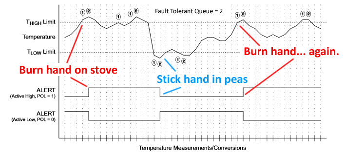
The AT30TS750A has the ability to trigger the alert pin based on a user configuration, and that is performed in the limit registers and configuration register. The low and high limit registers are exactly what you would expect them to be: values you place in the register in two’s complement format corresponding to the temperatures you want the system to use. How they are used is dependent on whether they are configured in comparator or interrupt mode, and what the fault tolerance queue length is. The alert pin will take an alarm state based on the polarity specified in the configuration register, so you can decide if you want it to be active low or active high.
In order to prevent the system from issuing false alarms, a fault tolerance queue is available, that basically means the sensor has to measure a value that exceeds the limits more than once if so configured. The fault tolerance queue can be set to require 1, 2, 4 or 6 consecutive faults before triggering the alert.
In comparator mode, an alarm is issued if the temperature exceeds the tHIGH limit and then remains there to satisfy the conditions of the fault tolerance queue. If it jumps through all those hoops and enter the alarm state, then the only way to exit the alarm, is for the temperature to drop below the tLOW threshold and remain there to, again, satisfy the fault tolerance queue conditions. This is like burning your hand on the stove and the alarms go off in your head until you jab your hand under a bag of peas in the freezer.
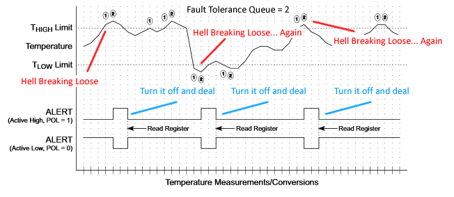
In interrupt mode, an alarm is issued when the fault tolerance queue condition is met by exceeding either threshold, low or high. The alarm state only remains active until a register read occurs or the device is placed in shutdown (an SMBus event will also turn off the alarm state, but we’re not using SMBus). The alarm is then disabled until it enters a safe period for a length of time that meets the fault tolerant conditions. Think of this as all hell breaking loose on the ship, and yes, you know the alarms going off, but you don’t need it blaring in your face, so you turn it off until you have shit back under control.
Remember that you would probably want to load up a value at the same resolution as the measurement you’re reading. Also, if your code switches from comparator mode to interrupt mode and back and forth again, you’ll want to really understand how these modes interact very clearly.
Configuration Lock
One of the important features of the configuration NVR, is that it has a lockdown measure for security. There are two ways to handle it.
There’s the warm and gentle caress of the RLCK bit set to 1, where you prevent any of the rest of the configuration or limit registers from being changed until you set RLCK to 0 again. I consider this security against my own stupidity.
Then there’s the Famous Archie Slap of the RLCKDOWN bit. If you set this one, your basically burning a fusible link inside the chip that can’t be unburned and you better like the way the thing was configured. This is a permanent lockdown. I consider this security against other’s stupidity.
Shutdown and One Shot Mode
The device can be placed into shutdown mode to conserve current consumption. In shutdown, it won’t do anything other than just sit there, waiting for the I2C bus to tell it to do something, saving a remarkable amount of current draw: 2.5µA vs 75.0µA when it’s not doing anything.
In shutdown, you can ping the device to have it do a single temperature measurement called a One Shot. Remember that you’ll need to take into account the conversion time based on the resolution you’re asking for. The temperature readings in one shot mode contribute to the fault tolerance queue, so it’s possible to trigger an alarm by doing so. However, the act of entering shutdown will cancel an interrupt alert, so you have to be careful how you configure it.
General Call Reset
When the Arduino sends out a General Call I2C address of 0x00, followed by a write flag, the AT30TS750A will respond with an ACK. At that point, you can send the reset opcode of 0x06. That opcode will execute the equivalent of a power on reset, and force the NVR configurations to overwrite the volatile ones.
